Point clouds
Point clouds are groups of measured points on the surfaces of objects created with 3D laser scanners, such as Trimble X9 3D Laser Scanning System. In construction, the point clouds are mainly used in renovation projects to define the building or structure that is to be renovated. They can also be used to get the exact position of existing machinery, pipework, or landscape that need to be taken into consideration on the site. You can also use them to check execution by importing them as build points into a model to be compared to the design.
About point clouds in Tekla Structures
- You can attach a point cloud locally, from the internet, or using the Trimble Reality Capture platform service (TRCPS).
-
Local point clouds:
- The original, attached point cloud file is processed and cache files are created in the potree format. The point cloud conversion occurs as a background process, and you can continue working with Tekla Structures meanwhile.
- Point cloud data is stored in the folder defined by the advanced option XS_POINT_CLOUD_CACHE_FOLDER. By default, the folder is
%LocalAppData%\Trimble\Tekla
Structures\PointClouds, for example, C:\Users\<user>\AppData\Local\Trimble\Tekla
Structures\PointClouds. The
XS_POINT_CLOUD_CACHE_FOLDERadvanced option is user specific, and it is located in the File locations category in the Advanced options dialog. - If the point cloud file is in the potree format already, then the original file is used without any conversion or copying to the ..\PointClouds folder.
- If you have a point cloud on a local computer, you work with a model in a network folder, and you attach the point cloud from the local computer, no one else can see it, because it is on the local computer. Point clouds are always personal data.
- If the same point cloud is used in several models, it will not be converted again or duplicated when you attach it. If point clouds are identical, the existing converted file is used, otherwise the file is converted.
- It may be useful to use a network drive for the potree file in a project. The file will not be copied to the local computer.
-
Point clouds from internet:
- When you use point clouds through the internet, the point cloud web streaming cache is a common cache with Trimble Connect for Windows. You can define the cache folder using the advanced option XS_POINT_CLOUDS_WEB_CACHE in the File locations category in the Advanced options dialog. By default, the folder is %LocalAppData%\Trimble\Trimble Connect\Import, for example, C:\Users\<user>\AppData\Local\Trimble\Trimble Connect\Import.
- The cache usage improves the performance of the web streamed point clouds.
-
Point clouds from Trimble Reality Capture platform service:
- When you attach and show point clouds stored in Trimble Reality Capture platform service (TRCPS), you do not need to store large point clouds files locally on your computer but you can attach point clouds hosted in an existing Trimble Connect project.
- Point clouds from Trimble Reality Capture are not converted to the potree format by Tekla Structures. The Trimble Reality Capture platform service in Trimble Connect does the conversion if needed when point cloud is uploaded there.
- Point clouds from the Trimble Reality Capture platform service use the same web streaming cache as the point clouds from the internet.
- Trimble Reality Capture platform service license is required for the point cloud provider (surveyor or other scanner owner) to store and share the scan data: Streaming point clouds from Trimble Reality Capture platform service does not require a separate license. The license is required for the point cloud provider to store and share the scan data in the Trimble Reality Capture platform service. Trimble Connect users can use the Trimble Reality Capture platform service by just toggling the button in the Trimble Connect user interface to access it. Users will get 10 gigabytes as free storage so it is easy to trial and if they need more storage beyond that they can purchase a license.
- To learn more about the service, see Trimble Reality
Capture.
Point clouds in Trimble Connect:
- When you attach a point cloud to a Tekla Structures model, you can place it either by the model origin or a defined base point.
-
In Tekla Structures, point clouds have colors if the original file format supports colors.
-
Point clouds can be seen in both the OpenGL model view and in the DX model view. The DX model view with perspective projection may give better visual results. Performance with a bigger amount of data and/or larger number of views is better with Open GL than DX rendering.
Compatible file formats
ASCII (.asc, .xyz)
E57 (.e57)
LAS (.las)
LAZ (.laz)
SDB (.sdb)
PTS (.pts)
PTX (.ptx)
Potree (.js, .json)
Trimble scan format (.tzf)
Trimble TDX format (.tdx)
Limitations
- Some basic Tekla Structures model handling functionalities are not available, such as select, undo, move, rotate, copy, and context menu on right-click.
- Point clouds are not autosaved.
- You cannot delete a point cloud from the point clouds list using the keyboard button Delete.
- Point clouds are not visible in drawings.
- Local point clouds are not shared in Tekla Model Sharing or in multi-user mode.
- For the file formats ASCII, PTS: On each text line, the first three fields must be: x y z. For colored point data, the last three fields must be: r g b
Attach a point cloud to the model
-
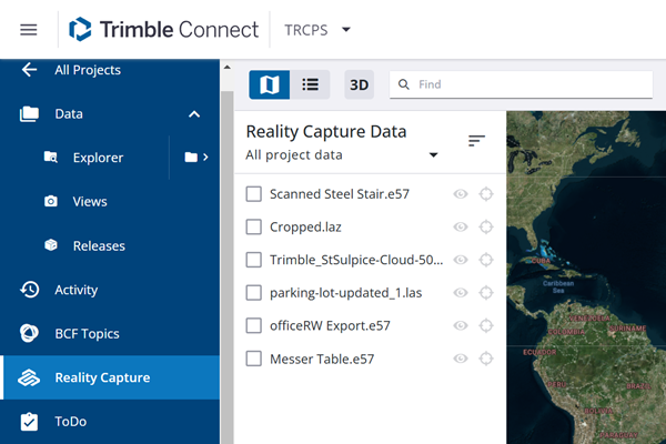
Click the Point clouds button
 in the
side pane.
in the
side pane.
-
Do one of the following depending on if you are attaching the point cloud
locally, from the internet, or using the Trimble Reality Capture platform
service:
- Attach a point cloud locally: In the Attach point cloud dialog, on the Local tab, browse for the point cloud file.
You can also drag point clouds from Windows Explorer, and insert several point clouds at a time.

- Attach a point cloud from the internet: In the Attach point cloud dialog, on the URL tab, enter the URL address of the point cloud.
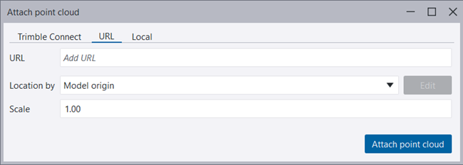
When you are using a point cloud from the internet, you need to create the HTTP directory structure potree that you can create with Point Cloud Manager.

-
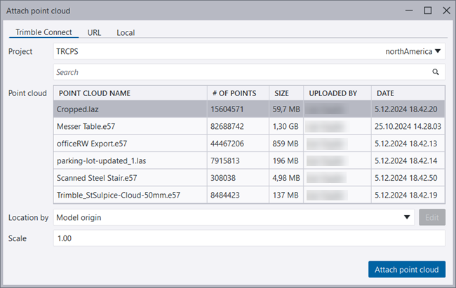
Attach a point cloud using Trimble Reality Capture: In the Attach point cloud dialog, on the Trimble Connect tab, select a Trimble Connect project hosted in the Trimble Connect project, and then select the desired point cloud.
The linked project will be selected by default. If no project is linked, the first project in the sorted list will be selected by default. The dialog will remember your previously selected project when reopened.
A loading spinner
 is displayed
while the point clouds for the selected project are being
loaded.
is displayed
while the point clouds for the selected project are being
loaded. You can browse to any Trimble Connect project that has point clouds in the service without needing to do anything specific in the Tekla Structures model.
You can also search for a point cloud.
Once the point cloud is attached, it will no longer be available for attaching again in the Attach point cloud dialog.
To learn more about the service, see Trimble Reality Capture.
- Attach a point cloud locally: In the Attach point cloud dialog, on the Local tab, browse for the point cloud file.
-
To show the point cloud in
the model, select the model view where you want to show it, and click the
eye button
 next
to the point cloud in the list.
next
to the point cloud in the list.
When you select a model view, the view gets a yellow frame.
When the point cloud is set visible in the model view, you can see the min x, min y, and min z coordinates of the point cloud bounding box on the status bar.
To hide the point cloud, click the eye button
 .
.
When you are modeling, you can snap to points for modeling and measuring distances. You can use clip planes and clip boxes in point clouds to show exactly what you want, for example, clip off the roof and some of the floors so that you can see the bottom floor of the building, and everything there that needs your attention in the planning phase. You can also use the Clipper tool in Tekla Warehouse for handling several clip planes at a time, and split the model to smaller pieces for visualization and modeling.
Modify point cloud properties and visualization settings
You can modify the point cloud properties and visualization settings when you have attached a point cloud, and DirectX rendering is active.
The point cloud Visualization settings are view specific and settings are enabled for one view only, the name of which can be seen at the top of the Point clouds side pane (if you have not selected multiple views). The Properties settings are enabled only if the point cloud is selected from the list.
-
When you have attached the
point cloud, select it from the point clouds list in the side pane,
otherwise you cannot modify its properties.

-
In Visualization settings - Depth perception (EDL), use the EDL (Eye-dome lighting) effect to improve the depth perception
of the point cloud. Drag the sliders to increase or decrease the outline
thickness and strength of the point cloud. You can deactivate the EDL effect
by clicking the EDL button.

-
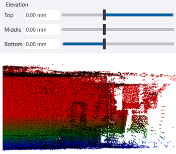
In Visualization settings - Elevation, change the point cloud colors. Normally, the default color values are in
use. The visualization settings are view specific and therefore you can use
different settings in different views.
-
You can color the point cloud by elevation by dragging the sliders.
-
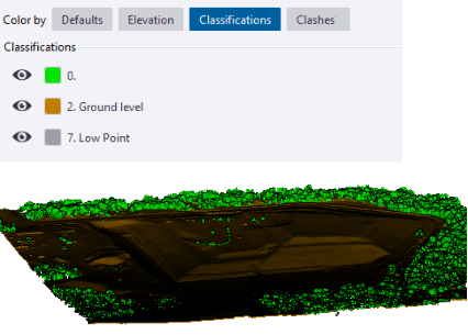
If the point cloud contains classifications, you can change the color of the classification category points or hide them in Visualization settings - Classifications.
-
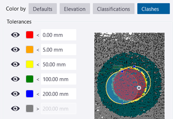
In Visualization settings - Clashes, check clashes and deviations by using different colors for different tolerances. You can detect points that are inside or within a distance from the selected parts and selected reference model objects based on the settings you define. Clash check between point clouds and pour objects is also supported.
Note that rendered objects coloring may cause confusing results. It is recommended to use Ctrl+1 and Shift+1 visibility modes to get unambiguous results.
-
-
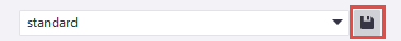
Save the properties and
visualization settings for future needs.
Detach a point cloud from a model
-
To detach a point cloud, click
 Detach next to the point cloud name in the Point clouds list. Then reopen the model or save the model.
 Note that you cannot detach the point cloud by pressing Delete on the keyboard.
The local point clouds are cached to the default location or to the location specified by the user. When a local point cloud is no longer used in any Tekla Structures model, it is cleaned from cache.
Set the default maximum point count in a view
You can use the advanced option XS_SET_MAX_POINT_CLOUD_POINT_COUNT to set the default maximum value for the points in a view. The default value is 10 000 000 (10 million). Restart Tekla Structures if you change the value.
Clip point clouds and reference models only
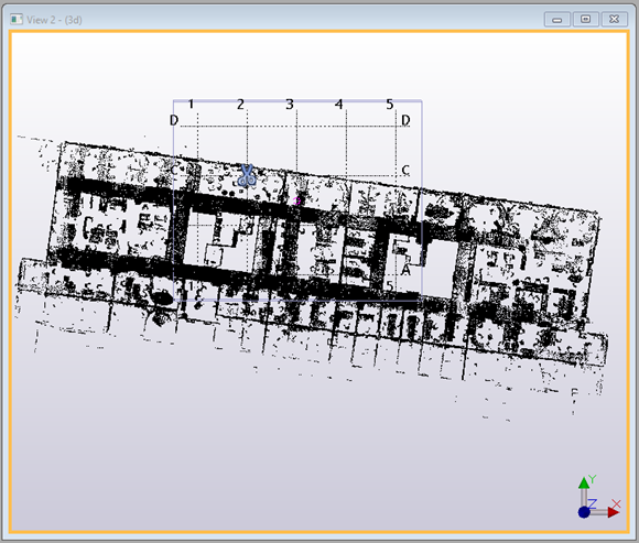
Point cloud example
In the first image below, a point cloud has been
attached to a model in a plan view. Remember to select a model view and click the
eye button  , otherwise the point cloud will
not be shown.
, otherwise the point cloud will
not be shown.
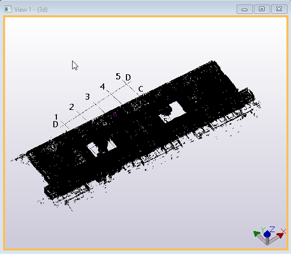
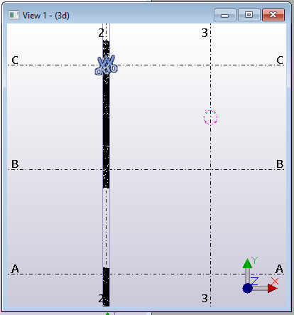
In the next image, the clip plane tool has been used to cut off floors and other structures:
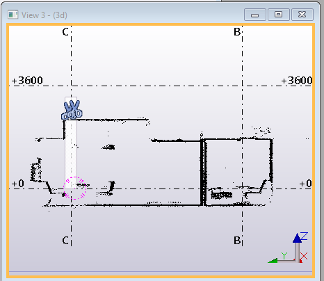
In the next image, a section has been cut to be used in a section view:
The last image shows the section view:
Share local point clouds with other users using potree file
Point clouds are normally so large in file size that it is not sensible to share the point cloud as a part of the model data. Point cloud is not structural domain data but project data that is not a part of the model, and therefore it is not dependent on the model save. However, there is need for multiple persons to use the same point cloud model efficiently. You can use the potree file for sharing the point cloud. The best practices in sharing the point cloud potree file among model users are explained below. You first need to create the potree file and copy the potree file to a shared location, and then other users can attach it to their Tekla Structures model.
Create a potree file
Option 1: With Tekla Structures
-
Create a potree file by attaching a point cloud model to a Tekla Structures model.
The potree file is created in the folder defined by the advanced option
XS_POINT_CLOUD_CACHE_FOLDER. The potree file is named as <potree_name>.db, and it has a folder with the same name. For example: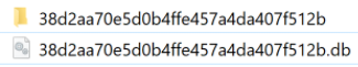
-
Copy both the <potree_name>.db file and the related folder to a shared location. You can rename the model if you want, in which case you also need to rename the folder.
 Note:
Note:Do not replace existing potree data, especially if it is used by other users.
Option 2: With Point cloud manager
For detailed instructions for creating a potree file with Point cloud manager, see section "Create a potree file with Point cloud manager" in "Hosting your own potree point cloud data".
Attach a potree from a shared location
-
Open Tekla Structures and the Point clouds pane from the side pane.
-
Browse to the point cloud folder (mypotree in the example above) and select the point cloud .js file. Then follow the instructions above for attaching the point cloud.