Export a drawing in 2D DWG, DXF, or DGN format
You can export Tekla Structures drawings in the 2D DWG, DXF, and DGN v8 format. You can export several drawings at a time.
The drawing export is object based. For example, if you export a rectangular part that is drawn using hidden line types, the result is a rectangular object drawn with a dashed line. In the old line-based DWG export, the result would be many separate short straight lines. Hatches are also exported as hatch objects in CAD and not separate lines.
In the drawing DWG/DXF/DGN export you can:
- easily set export layers or levels for different objects, and separate mark frames from mark text and leader lines, for example
- use filters to separate parts from other parts
- use export layers or levels that have been predefined by standard CAD layer/level settings
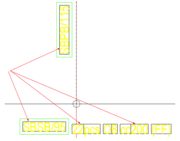
- use base points and model coordinates
- embed images in the export file so that the images are no longer exported as links
The drawing export does not use font conversion, and the resulting fonts match exactly the fonts that you haven defined and see in the Tekla Structures drawing. With the advanced option XS_DRAWINGS_USE_CAP_HEIGHT_FOR_FONT_HEIGHT you can control which font height system to use in drawings, CAP font height or em font height.
Define export settings and export DWG, DXF, or DGN files
-
Start the export in any of the following ways:
- On the File menu, click , and select the drawings from the displayed Document manager list.
- Click
, select the drawings that you want to export from
the Document manager list, right-click and select Export, or click the
 Export button at the bottom. The Export command is not available when you open the Document manager in the drawing mode.
 - In an open a drawing, on the File menu, click Export drawings.

-
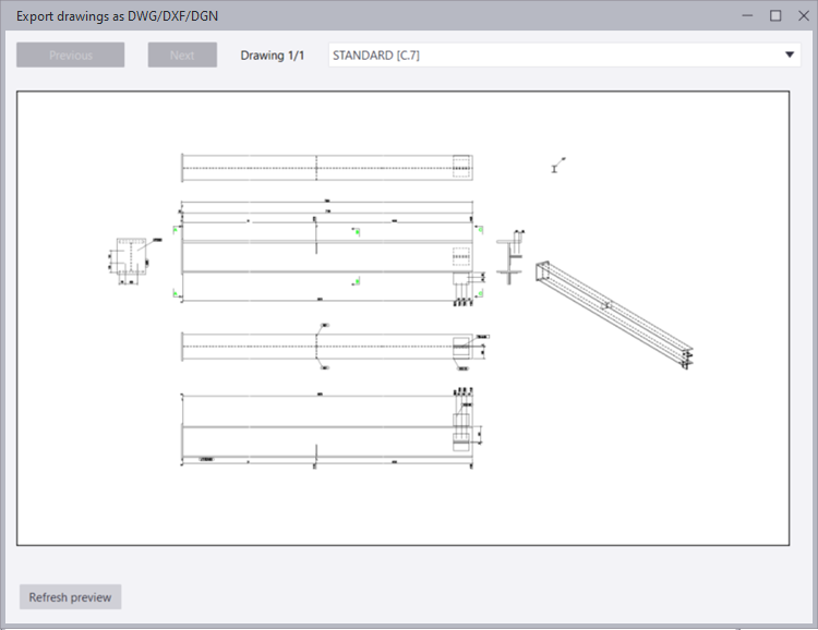
Click Open preview to show the preview window, where you can also change the displayed
drawing if you have selected many drawings for export. To get the preview
visible for the first time, click Refresh preview. You can refresh the preview again by clicking Refresh preview. The preview does not get refreshed automatically, because this could
take a long time.
-
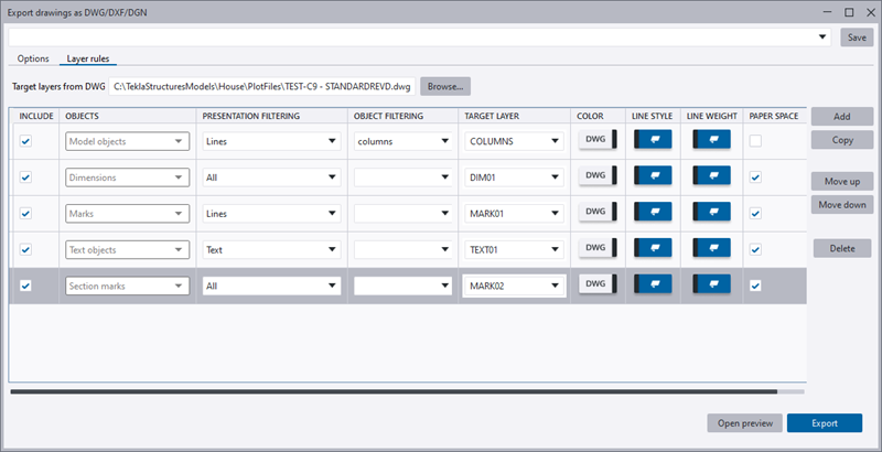
On the Layer rules (DWG, DXF) or Level rules (DGN) tab, you can define explicitly the layers or levels where different
model and drawing objects, or parts of objects are exported to. For example,
you can export outlines to a different layer or level than fills and
hatches.
You can also define whether the line color, style, and weight will be used from Tekla Structures settings or from the target layer or level settings specified in a DWG, DXF, or DGN file. If you select Tekla Structures settings, Tekla Structures line color, style, and weight stay exactly as you see them in the Tekla Structures drawing, and there is no functionality to modify them just for the drawing export.
DWG layer rule example
In the example below, three separate mark rules have been created that will be exported on layers 1, 2, and 3. Lines are exported on the layer 1, texts on the layer 2, and frames on the layer 3.
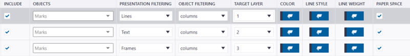
After exporting, you can show the marks in the CAD model in the following three ways depending on the layers displayed in the CAD viewer:
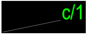
All layers are shown:

Layer 1 containing the lines is hidden:

Layer 2 containing the texts is hidden:

Layer 3 containing the frames is hidden:
Tips
-
If you use the Output file version 2013 in the export, a wipeout frame will be visible on the layout side in the CAD model due to the limitations in CAD, see below:
To avoid this, either use a DWG file layer template created in AutoCAD, or use the output file version 2010 (default) or earlier.
-
Another reason for the visible wipeout frame is that you are using a DWG template where wipeout frames have been set visible. Hide the wipeout frames in the CAD template. For more information, see "Remove unwanted text frames from DWG exports".
To use old DWG or DXF drawing export
If you want to use the old DWG or DXF drawing
export, set the advanced option XS_USE_OLD_DRAWING_EXPORT to
TRUE
in an .ini file. This advanced option is by
default set to FALSE. For instructions on using the old export, see Export a drawing to a
2D DWG or DXF file (old export).