Define automatic reinforcement and reinforcement mesh properties
You can define what is shown in reinforcing bars and meshes and how they are shown in cast unit and general arrangement drawings. You can also do this for neighbor reinforcement.
Tip:
- The representation of reinforcing bars that point away from the drawing can be changed. You
can customize reinforcing bar bent symbols (cross, circle, filled circle) by
editing the symbol file bent.sym, which in the default
environment is located in the folder ..\ProgramData\Trimble\Tekla
Structures\<version>\\environments\common\symbols. Or, you
can create a new symbol file in the same folder, for example,
my_new_symbols.sym, and take it into use in the rebar_config.inp by
entering the following string in the file:
BentSymbolFile=my_new_symbols.sym - If you wish to show embeds while hiding reinforcement, use the XS_HIDDEN_LINES_UNHIDE_EMBEDDED advanced option.
Example: Reinforcement representations
Here are examples of how the reinforcement will look with the different representation options selected on the Bar content tab in Reinforcement or Neighbor reinforcement properties.
| Setting | Example |
|---|---|
|
single line |
|
|
single line with filled ends |
|
|
double lines |
|
|
double lines with filled ends |
|
|
filled line |
|
|
stick |
|
|
outline |
|
Example: Hide reinforcing bar lines in drawings
You can hide reinforcement bar lines behind other reinforcing bars and behind parts in cast unit drawings. Here are some examples of what reinforcing bars look like with different settings selected on the Bar content tab in Reinforcement or Neighbor reinforcement properties.
| Setting | Example |
|---|---|
|
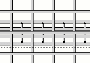
Hide lines behind parts is selected. The reinforcing bar lines are hidden behind other parts. In the image, the hidden bar lines and shown dashed. |
|
|
Hide lines behind other rebars is selected. The reinforcing bar lines are hidden behind other reinforcing bar lines. In the image, the hidden bar lines and shown dashed. |
|
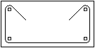
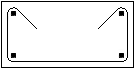
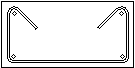
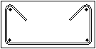
Example: Rebar assembly representation
Here are some examples of what rebar assemblies look like with different settings selected on the Rebar assembly tab in Reinforcement or Neighbor reinforcement properties.
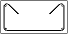
| Outline is selected. All sub-assemblies of the rebar assembly are shown as outline boxes. | 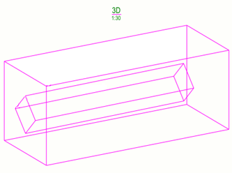 |
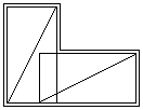
| As individual rebar objects is selected. All rebar objects in the rebar assembly and sub-assemblies are visible. | 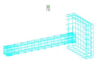 |
|
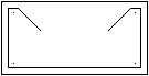
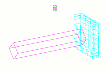
Sub-assemblies as outline, highest level as individual rebar objects is selected. All sub-assemblies are shown as outline boxes and the highest level of the rebar assembly is shown as individual rebar objects. |
 |