Show fillet edges in drawings
Fillet edges are lines that define the boundary between straight faces and curved faces in the model. Some examples of building objects containing fillet edges are profiles with curved fillets, slabs or contour plates with curved chamfers, and curved polybeams. The fillet edges can be shown in all drawing types for parts and pours. Fillet edges are visible by default for new drawings, and invisible for drawings that are created in a Tekla Structures version earlier than 2016.
Show fillet edges in GA drawings
To show the fillet edges, you need to set Fillet edges visible in part properties. For profiles, the Exact representation might be required to show the fillet edges, depending on the profile. You can control the fillet edge visibility in part properties and in pour object properties on the drawing, view and object level.
To set the fillet edges visible on the drawing level in a general arrangement drawing:
Show fillet edges in individual parts
-
In the Visibility section, activate the Fillet edge option
 .
.
Examples
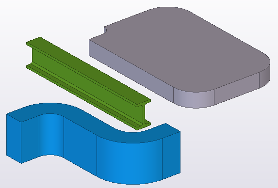
Example 1
Below is an example of fillet edges in the model:
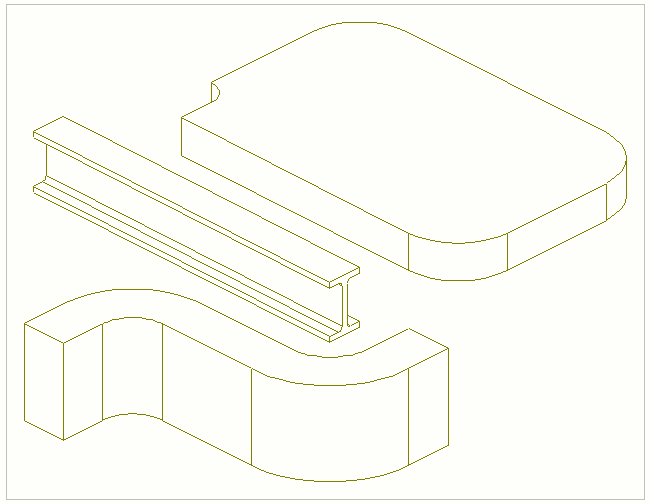
Below is an example of parts in a drawing
showing the fillet edges (Fillet edges on/off selected in
the drawing level part properties or Fillet
edge selected in part properties in the property pane):
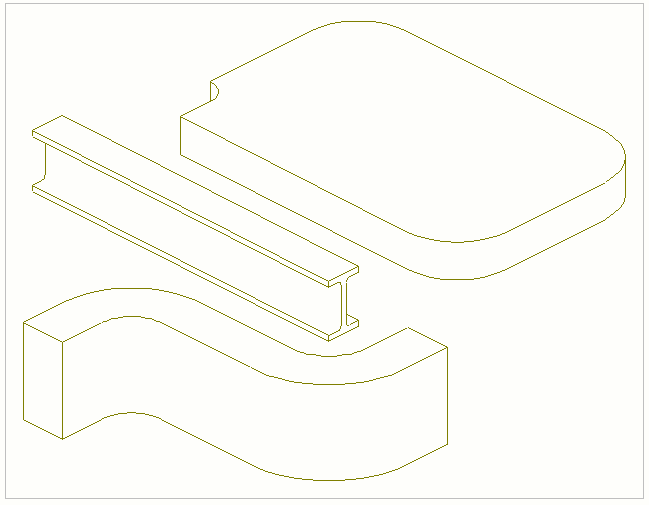
Below is an example of parts in a drawing not
showing the fillet edges (Fillet edges on/off not
selected in the drawing level part properties or  Fillet
edge set in part properties in the property pane):
Fillet
edge set in part properties in the property pane):
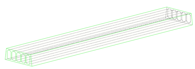
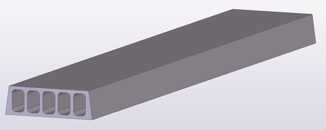
Example 2
Below is an example of a hollow-core slab in the model:
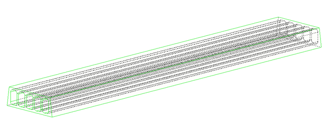
Below is an example of the hollow-core slab in
a drawing showing the fillet edges (Fillet edges on/off
selected in the drawing level part properties or Fillet
edge set in part properties in the property pane). As you can see,
the representation is not very clear when the fillet edges are visible:
Below is an example of the hollow-core slab in
a drawing not showing the fillet edges (Fillet edges
on/off not selected in the drawing level part properties or Fillet
edge set in part properties in the property pane):