Create and edit drawing layouts
Use Drawing layout editor to create new drawing layouts and edit existing ones. Working on the layout, you can add, modify, move, and remove tables, add and modify drawing sizes, and select if you want to see table names or hidden tables in the drawing layout. In Drawing layout editor, you can also add frames and fold marks in drawings.
Open Drawing layout editor
To access Drawing layout editor, do any of the following:
|
To access Drawing layout editor |
Do this |
|---|---|
|
Through the File menu in modeling mode or drawing mode |
|
|
Through a drawing properties dialog |
|
|
Through the ribbon in the modeling mode |
|
|
In an open drawing |
Do any of the following:
|
|
Through Quick Launch |
|
Create a new drawing layout
-
In Drawing layout editor, on the Layout editor ribbon, click
 Create layout.
The drawing layout is saved in the \attributes folder under the model folder as a .lay file. Note that the .lay files are not compatible with the Drawing layout tool or the Layout editor that were available in older versions of Tekla Structures. This means that you cannot use the new layout with older versions of Tekla Structures.
You can now continue working with
drawing layouts or close the layout editing mode by clicking  Close Layout editor.
DWG/DXF files and keyplans in layouts
DWG/DXF files
- If the DWG/DXF file can be found under the current model folder, a relative path (current model/project/firm/env) will be used, otherwise absolute path is used. If you want to use a relative path, first copy the DWG/DXF file in your model folder and insert it from there. The path to your DWG/DXF file will then be defined with path ".\", which will in run time evaluate using same search order as other layout content.
- DWG/DXF files cannot be rotated in the layout.
Keyplans
- Keyplans need to be scaled in the original drawing.
- Keyplans are shown in drawings even if the layout was created in a different language than what is used when the drawing containing the keyplan is opened.
- You cannot insert multiple keyplans in one layout.
- Keyplans cannot be rotated in the layout.
Add tables to a drawing layout
-
On the Layout editor ribbon, click
 Add tables.
Move tables in drawing layout
-
In the drawing layout, do
either of the following:
- To move one table, click the table that you want to move.
- To move several tables, hold down the left mouse button and drag a box around the tables that you want to move.
Two green handles appear.
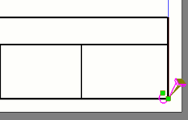
The handle that is further from the table determines where the table is anchored. The closer handle determines where one corner of the table is located.
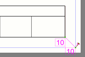
The tables are moved to the new position.
Replace tables in drawing layout
- In an open drawing layout, right-click a table that you want to replace.
- In the context menu, select Replace table.
- Select a new table from the Replace table dialog and click Replace.
Remove tables from drawing layout
Do any of the
following:
- In the drawing layout, right-click a table and select Delete.
- In the drawing layout, click a table and press Delete on the keyboard.
- Select a table in the Tables in use list and press Delete on the keyboard.
Adjust drawing sizes, frames, and fold marks
Frames and fold marks can be customized individually for each drawing layout, or .lay file. However, the frame properties are initially read from the standard.fms file with global frame and fold mark properties. If you do not want to use the global frame and fold mark properties in a drawing layout, adjust the appropriate properties in the Drawing size settings dialog.
-
In the Layout editor side pane, click the
 Edit button on the right side of the Drawing size list.
-
In the Sizes in use section in the Drawing size settings dialog, edit the drawing sizes according to your needs:
To Do this Add a new drawing size
-
Click the plus button
 under the list of existing drawing sizes.
A new line is added at the bottom of the list of drawing sizes.
-
Either select a predefined drawing size from the list in the Name column, or type a name for the new drawing size.
The predefined drawing sizes in the Name list are defined in the PaperSizesForDrawings.dat file. By default, the file is located in the ..\ProgramData\Trimble\Tekla Structures\<version>\environments\common\system folder folder.
-
To adjust the width and height, double-click the Width and Height boxes and type new values.
You can also right-click the size row, select Edit and type the width and height in the displayed dialog.
-
If you want to allow Tekla Structures to use the drawing size when automatically selecting suitable drawing sizes for drawings, select the Autosize checkbox.
For more information on autosizing, see Define drawing size and drawing view scale.
Adjust the width and height of a drawing size
-
Select the drawing size whose width and height you want to modify.
-
Double-click the Width and Height boxes and type new values.
You can also right-click the size row, select Edit, and define the width and height in the displayed dialog.
Change page orientation -
Right-click the row of the drawing size whose orientation you want to change.
-
Select Swap orientation.
The width and height of the drawing size are swapped.
Enable using the drawing size for automatic drawing sizes
-
Select the drawing size that you want to use in autosizing.
-
Select the Autosize checkbox.
Delete a drawing size from the drawing layout
-
Click the remove
 button next to the drawing size that you want to
delete.
button next to the drawing size that you want to
delete.
-
Adjust the position of drawing views
To adjust the position of drawing views, you need to have a drawing open.
Note that the Drawing views settings work together with the XS_DISABLE_VIEW_CENTERING_[drawing type] advanced options. By setting the values of these advanced options to VER, HOR, or both, you can disable automatically centering drawing views in horizontal, vertical, or both directions.
You can enable or disable centering of drawing views manually for all drawing types except for cast unit drawings. In cast unit drawings, centering of drawing views is always enabled.
Adjust the visibility of tables in the drawing layout
The drawing layout contains some information that you may not always need to see, because some tables are not relevant in all drawings that use the same drawing layout. These tables are called hidden tables. If the content of a drawing changes, these tables may appear again. For example, a table may become visible if you add a revision.
By default, hidden tables are shown as simple boxes that have a known width and a default height. In the image below, the upper table is a regular table, while the lower table is a hidden table.

If necessary, you can choose to hide hidden tables from the drawing layout completely.
Do any of the following:
| To | Do this |
|---|---|
| Hide or show hidden tables |
|
| Hide or show table names |
|
 next to
  next to
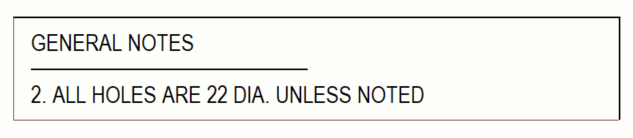
Edit a drawing layout
Tip:
You can remove or rename drawing layouts in the file folder. Go to the \attributes sub-folder under the model folder, find the right .lay file, and remove or rename the file.
The changes that you made are saved to the drawing layout (.lay) file. All drawings that use the edited layout are automatically updated to match the changes.
You can now continue working with drawing layouts or close the layout editing mode by clicking Close Layout editor.