Tables in drawing layout
Tables are Template Editor templates added in Tekla Structures drawings containing information on model objects. In Template Editor, the tables are referred to as graphical templates.
The term table refers to various elements in a drawing layout, such as:
-
Tables (such as revision tables) created in Template Editor (.tpl)
-
Title blocks created in Template Editor (.tpl)
-
Lists (such as part and bolt lists) created in Template Editor (.tpl)
-
General notes created in Template Editor (.tpl)
-
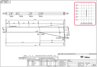
Key plans: A keyplan is a small map in a drawing that shows the position of an assembly, a cast unit, or a part in the model. To create a keyplan, you need to use a drawing that contains only one view of the correct scale and size. The keyplan usually includes the model grid and the assembly, cast unit, or part shown in the drawing. Tekla Structures automatically includes the correct object in the keyplan. Tekla Structures only uses the view from the original drawing, and the view position, drawing size, and templates of the original drawing are not relevant to the keyplan.
-
DWG/DXF files: For example, you might have some details in a DWG or DXF file that you want to show in certain types of drawings and therefore add the file in the drawing layout.
If you change the model, Tekla Structures updates the contents of the affected drawings and tables created in Template Editor. The contents of the tables are filled in by Tekla Structures at run time.
The available graphical templates are read from the following folders in the following order, and shown in the Available tables list in the Layout editor side pane:
- Template folder (
XS_TEMPLATE_DIRECTORY) - Current model folder
- Project folder (
XS_PROJECT) - Firm folder (
XS_FIRM) - Environment-specific system templates folder (
XS_TEMPLATE_DIRECTORY_SYSTEM) - System folder (
XS_SYSTEM)