Other enhancements and fixes
In addition to the major feature highlights, many other improvements to modeling, design and other areas were made after the first release of Tekla Structural Designer 2024.
General & modeling
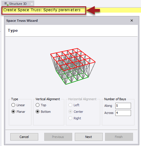
[TSD-8729] - Space Truss Wizard Command Prompt
Step descriptions for the Create space truss operation have been added in this release.
Improved View Information for Column and Walls
The following enhancements have been made.
-
[TSD-15394] - New View Text 2D for Name and Attributes
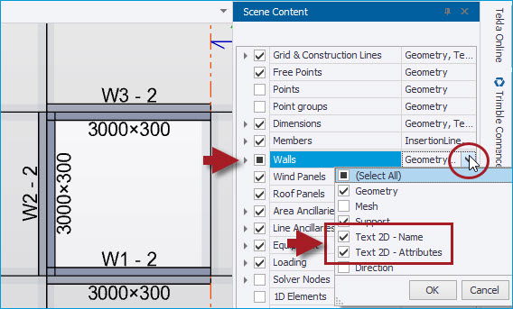
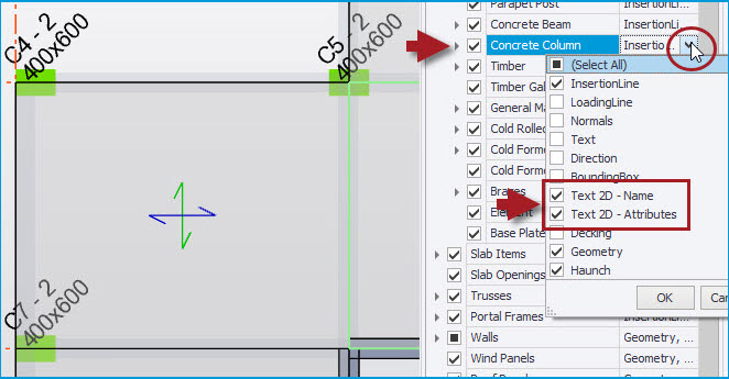
The Name (default or user name) and/ or Attributes (dimensions/ thickness and (steel) grade) of columns and walls (of all materials/ types) can now be displayed in 2D plane views. As shown in the pictures below, the viewing of this new text is enabled via the Scene Content checkboxes for “Text 2D- Name” and “Text 2D- Attribute” for walls and columns.
-
[TSD-16901] - Name text improved to distinguish columns and walls terminating without direct support
The base levels of columns and walls that terminate without a direct support are now distinguished in 2D views by the text “(BASE)” being appended to their reference, as illustrated in the picture below. The purpose of this is to highlight transfer locations (columns or walls supported by beams or slabs). This can also highlight unintentional mis-modeling, e.g. separate columns or walls stacked one on top of the other.
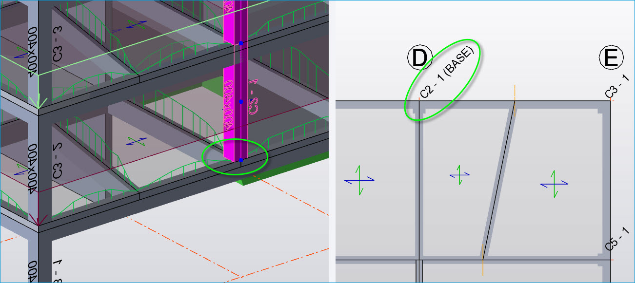
-
[TSD-16876] - Wall Panels - New Direction Arrow
A new Scene Content option to display the direction of walls is added - when this is enabled, an arrow is displayed in the view on each wall panel showing its positive direction i.e. that from the start insertion point to the end insertion point, as shown in the picture below. This assists in editing models and understanding results etc.
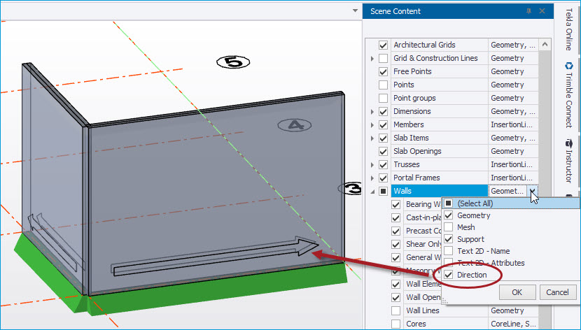
All of the above were already introduced in Tekla Structural Designer 2024 SP3
Reference Model Enhancements
The following enhancements have been made:
-
[TSD-16024] - Reference models - Transparency settings
New individual Opacity controls are provided for each layer on the Layers Filtering page of the Edit Reference Model dialog when importing a new reference model. For previously loaded models, the same Edit Reference Model dialog is accessed via the Edit context menu option on right-clicking over a model in the Reference Models Window list, as shown in the picture below.
To help with the performance of rendering large models, opacity defaults to 50% (128) for layers with a reasonable number of elements but is kept at 100% (255) for layers with a significantly large number of elements.
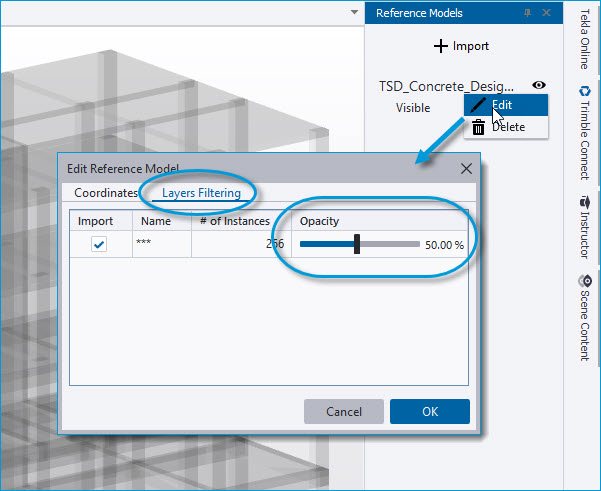
This enhancement was already introduced in Tekla Structural Designer 2024 SP3
-
[TSD-15946] - Reference models at real world coordinates
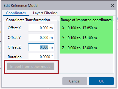
When the origin of a reference model uses real world coordinates (RWCs) it may be at a very different location to the model origin in Tekla Structural Designer. In these circumstances it can be challenging to determine the transformation required to position the reference model correctly in Tekla Structural Designer. To help with this, the Edit Reference Model dialog now shows the range of coordinates included in the reference model enabling you to more easily determine the required transformation coordinates.
For the case of multiple reference models all of which reference the same RWCs, the "Import from other model" option shown below enables the re-use of the Coordinate Transformation values of a previously imported model.
This enhancement was already introduced in Tekla Structural Designer 2024 SP3
-
[TSD-16849] - Scene Settings - improved operation of Opacity settings
All previous releases of Tekla Structural Designer have featured opacity controls in Global Settings > Scene > Colors in the form of sliders to adjust the opacity levels of entities in graphical views, as shown in the picture below. More recently these sliders have also been implemented for layers when importing reference models. These controls are improved to make them simpler and more practical to use as follows:
-
The slider range is now between 5% and 100%, in place of the previous 0 to 255.
-
When moved with the cursor, the slider snaps at 5% intervals and existing levels are rounded to the nearest 5%.
-
Cursor clicks on the slider track now move the slider by 25% instead of 1% at a time.
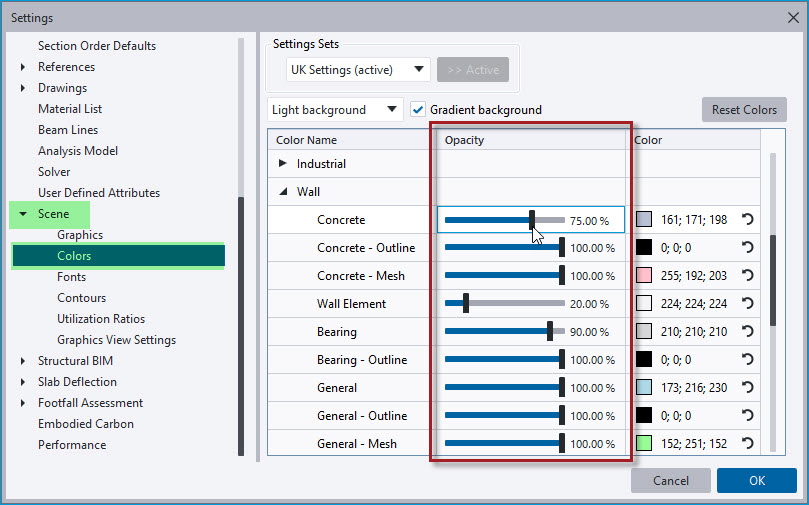
This enhancement was already introduced in Tekla Structural Designer 2024 SP3
[TSD-8713] - Steel Section Database - new range of Tata Hot finished Celsius products added
CHS, RHS and SHS Tata Steel Celsius hot finished hollow sections have been added to the steel sections database.
Steel grades 355NH, 420NH, 460NH for Tata Steel Celsius hot finished hollow sections have also been added to the TSD Materials database for all Eurocode regional codes.
This enhancement was already introduced in Tekla Structural Designer 2024 SP2
[TSD-14105] - DXF Shadow now included in report images
When an imported DXF shadow layer is visible in the interface for a saved view configuration the shadow will now also be included in the report View item set to that view configuration.
This enhancement was already introduced in Tekla Structural Designer 2024 SP2
[TSD-15806] - New Region Settings set for Mexico
-
Units = Metric
-
Steel Section Database - new “Mexico” country database with US metric steel sections with customary designations (see picture below)
-
Concrete Reinforcement Country = USA
-
Region Design Code - United States (ACI/AISC)
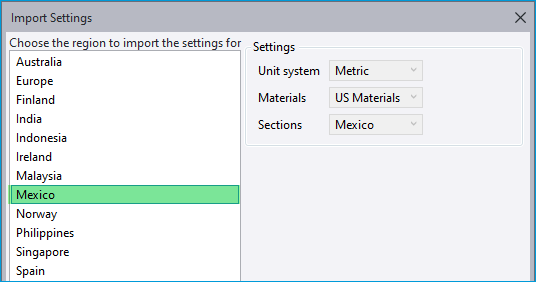
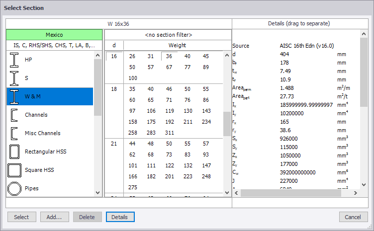
The new settings set can be selected as the default active set when first running the program (for a completely new installation) or via Home > Settings > Settings Sets > Import… as shown in the picture above.
While it is not set automatically, note that Spanish can also be set as the Interface language via Home > Settings > “Select the preferred language” as shown in the picture below.
Note that when the preferred language is set = Spanish, the terms used in the concrete/ steel design details in dialogs and reports are still in English.

This enhancement was already introduced in Tekla Structural Designer 2024 SP2
[TSD-13563] - Metal Decking Database - New ComFlor® 51+ Metal Deck profile added
Tata ComFlor® 51+ data has been added to the metal decking database for Europe, UK and Ireland. Note the older Corus Comflor 51 and Tegral Comflor 51 are both retained in the metal decking database.
This enhancement was already introduced in Tekla Structural Designer 2024 SP1
[TSD-14459] - Steel Sections Database - New US AISC sections added
The AISC steel sections database has been updated to include the new shapes introduced by the 16th version of AISC's official section shapes database. 222 new sections have been added for US steel design - 6 W, 6 WT, and 210 HSS (64 circular, 127 rectangular, and 19 round).
This enhancement was already introduced in Tekla Structural Designer 2024 SP1
[TSD-15995] - Review view - Slab/ Foundation Reinforcement view enhanced
The Review View > Slab/ Foundation Reinforcement review mode has been enhanced to simplify working with slab patch reinforcement in the situation of a more congested arrangement of multiple patches for both top and bottom surfaces. When reviewing patch reinforcement, the surface (top or bottom) and reinforcement direction (X or Y) are now specified in the Properties Window. In previous releases all patches were displayed regardless of their surface and rebar direction, with some of them being marked as "N/A". This could produce a confusing view and cause problems with reviewing and editing patches relevant to the selected surface/ direction. Now only patches relevant to the selected surface/ direction are displayed. This is illustrated in the picture below.
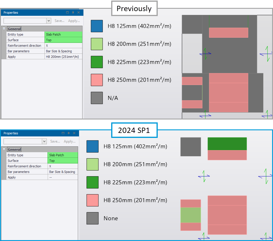
An additional reinforcement level = "None" has also been added for patches that do not require additional reinforcement - in previous releases these patches were also marked as "N/A".
This enhancement was already introduced in Tekla Structural Designer 2024 SP1
Loading
[TSD-17286] - Wind Loading Eurocode Roof zones - references
When defining wind zone panel properties for multibay roofs, the factors to apply should be taken from EN1991-1-4 Fig 7.10.
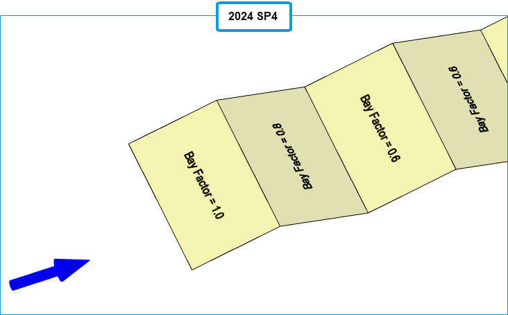
In previous releases, in the Wind Direction view each Multibay panel was labelled as Upwind Bay, Second Bay or Third and More Bay according to the "Bay Position" property you set for each panel in the Properties window. The factors would then be determined accordingly. The drawback with this approach is that it didn't allow you to visually confirm the factors being used.
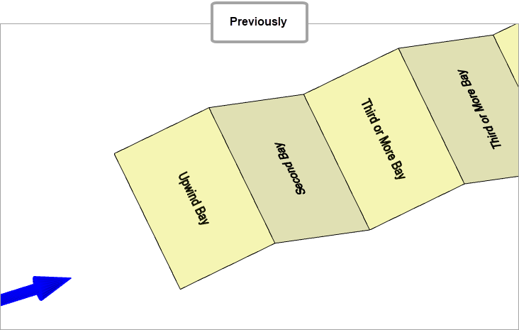
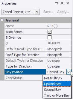
To clarify the actual factors being used, "Bay Position" has now been replaced by "Bay Cpe Multiplier". This enables you to set the panel factors directly as Bay Factor = 1.0, Bay Factor = 0.8 or Bay Factor = 0.6.
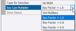
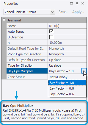
A tooltip for "Bay Cpe Multiplier" provides the reference to be used (EN1991-1-4 Fig 7.10) when choosing the factor to apply.
This enhancement was already introduced in Tekla Structural Designer 2024 SP4
[TSD-15739] - Member loads - Option to adjust load position when it becomes invalid
When the loading segment of a member changes, this can cause member loads to be moved beyond the end of the member, which causes a model geometry error. This may typically happen when an exterior concrete column size is increased, affecting member loads on a supported beam. Since member loads are positioned relative to the start of the loaded length, if the member load is already at the very end of the loaded length, an increase in column size can shorten the loaded length and "push" the load, or part of it, off the end of the member, causing it to be invalid and producing a validation error. To more easily resolve such cases, new “Reposition”and “Shorten” options have been added to the right-click menu for the error in the Status tree, as shown in the picture below.
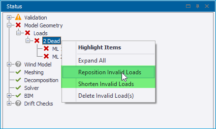
The options work as follows:
-
Reposition - applicable to both distributed and point loads
-
Point loads - are moved back to the end of the beam.
-
Distributed loads - the length of load is retained and the start position changed so it is fully on the beam.
-
-
Shorten - applicable only to distributed loads - the start position is maintained and the length changed.
This enhancement was already introduced in Tekla Structural Designer 2024 SP1
Interoperability
[TSD-16751] - Grasshopper Live Link enhancements for working with sections
The Grasshopper - Tekla Structural Designer Live Link has been enhanced to improve selection and filtering of sections with two new components and one updated component as follows.
-
New Section Geometry component - this outputs the selected Section Geometry from the list of available section geometries.
-
New Section Group component - this takes the Section Geometry as an input and will output either a selected section group, or all available section groups for the selected geometry.
-
Updated Section Filter component - this has been adjusted so that the user no longer specifies the Section Geometry and Group from a dropdown selection. Instead, the Section Group is input to the component.
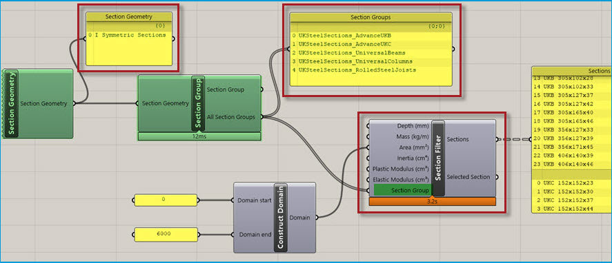
For the new inputs to the Section Group and Section Filter, it is now possible to combine different outputs from the upstream components to enable multiple selections to be included in the filter as shown in the picture below.
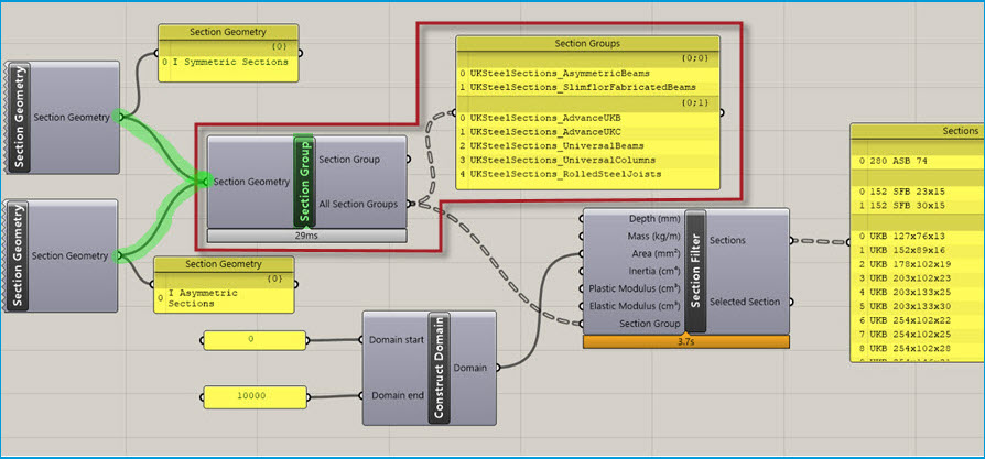
The main intention is to use the output of the upstream components to the new inputs as illustrated above. However, as shown below, it is also possible to provide a text input to the Section Geometry input on the Section Group component, and also the Section Group component on the Section Filter component.
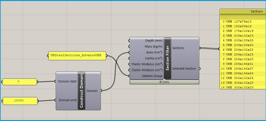
This enhancement was already introduced in Tekla Structural Designer 2024 SP3
[TSD-16553] - Grasshopper Live Link - improved Sections Filter performance
For the Grasshopper - Tekla Structural Designer Live Link, an issue introduced in a previous release which increased the load time of the Section Filter component has been fixed, reducing the load time by a factor of around 10x or more vs that in previous releases.
This enhancement was already introduced in Tekla Structural Designer 2024 SP2
[TSD-15551] - Review View - Show/Alter State BIM Status enhancements
The functionality of Show/Alter State BIM Status has been enhanced to allow for the displayed BIM Status to be filtered according to the UDA values (for example phases) that have been assigned to entities via the new “UDA” control, as shown in the picture below.
The existing filter controls are also improved with the previous “Characteristic” setting being replaced by “Variant” as shown below right. The “Variant” option is only displayed when an Entity type - such as “Member” as shown - is selected, with the drop down options list being automatically populated with only those variants contained in the model.
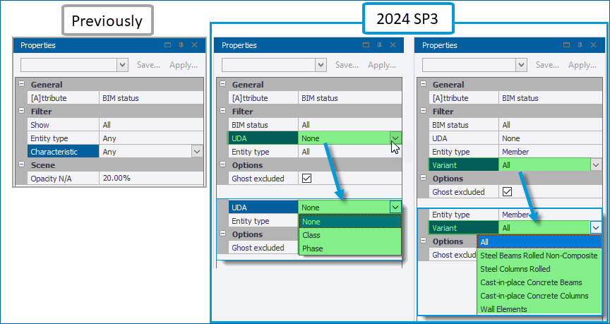
This enhancement was already introduced in Tekla Structural Designer 2024 SP3
Remoting API Enhancements
Some enhancements have been made to the Open API - for information about these see the Tekla Structural Designer 2025 Open API Release Notes.
For information about the previous enhancements made in the 2024 Open API service packs see the Tekla Structural Designer 2024 Open API Release Notes.
Validation
[TSD-17480] - Warnings issued for wind loads decomposed to rigid diaphragms
-
For simple wind loads decomposed to diaphragms - when you run model validation a warning will be displayed if the building has wider rigid diaphragms above levels with narrower rigid diaphragms, (a typical example might be a building with small mezzanine levels or landing levels in stairs modelled with diaphragms).

If the above validation message occurs, you should check that the total load applied and/or the decomposed load value acting on each diaphragm is approximately what you would expect. You can then manually apply any missing simple wind loads if necessary.
-
For loads generated by the Wind Wizard - during analysis an extra check is now performed to confirm the Decomposable Loads equate to the Total Load on Structure. If the check fails a warning is displayed against the wind loadcase in the Project Workspace Loading window.
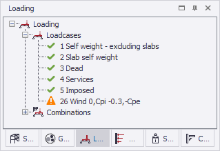
A description of the warning is also displayed in the Process Window.

If the Process Window warning occurs, you can use the Project Workspace Loading window to select the loadcase in question in order to compare the Decomposable Loads against the Total Load on Structure in the Properties window. If necessary, set the wind walls to decompose to members or nodes instead of rigid diaphragms to resolve the issue.
[TSD-17252] - Warning issued when foundation mat not meshed in 3D
The existing validation warning "Foundation mat with ground bearing springs not meshed" that is displayed when a foundation mat with ground bearing springs is not meshed has been updated.
Tekla Structural Designer now checks and warns for any foundation mat that is not meshed, irrespective of whether it has the "Use Ground Bearing Springs" property selected or not.

This enhancement was already introduced in Tekla Structural Designer 2024 SP4
[TSD-15229] - Panels - improved location of spanning issue indicator arrow
For one-way spanning panels with the validation error "Panel is not surrounded by load carrying members”, the location of the blue arrow indicating the problem, displayed in the view on double-clicking the validation error, has been improved. Previously it would point to the panel but not to the specific coordinates indicated in the validation error, which could make it difficult to locate the cause of the issue. The validation error coordinates are now used to determine the placement of the location arrow, allowing you to more quickly locate the problem in the view and take action - e.g. in the example below the arrow now points to the specific edge of the roof panel where the problem lies (that where it spans towards a brace member which does not support decomposed loads).
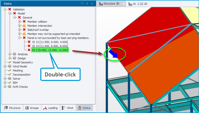
This enhancement was already introduced in Tekla Structural Designer 2024 SP3
[TSD-16687] - Loading - new validation for empty load cases
New validation checks and associated warnings have been added for Empty loadcases. As shown in the picture below, this issues an “Empty loadcase” warning in the Status > Validation tree with an explanatory tooltip. An option is then provided via the right-click context menu to delete any/ all of the empty loadcases that are listed. The new validation skips the "Self weight - excluding slabs" and "Slab self weight" cases when their “Calc Automatically” setting is enabled (the default) but will list them when this is disabled and they are otherwise empty.
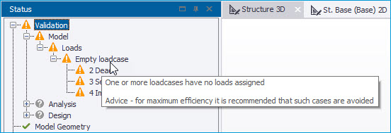
This enhancement was already introduced in Tekla Structural Designer 2024 SP3
Design - General
[TSD-17152] - Beams with haunches - default restraint at sharp end of haunch
For steel members with haunches (including portal frame rafters as illustrated below), the default restraint at the sharp end of the haunch has been changed from bottom flange, to being unrestrained.
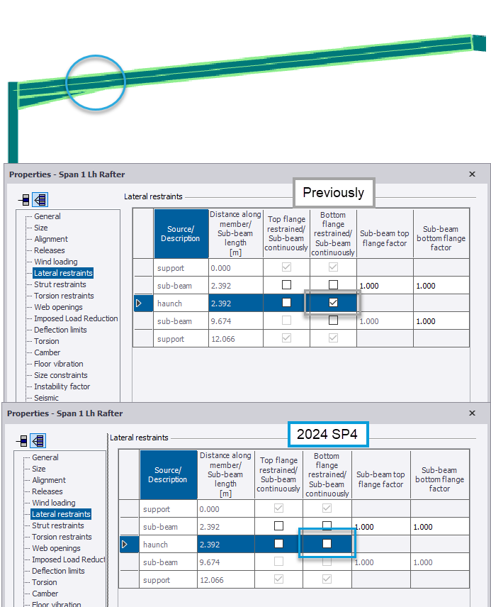
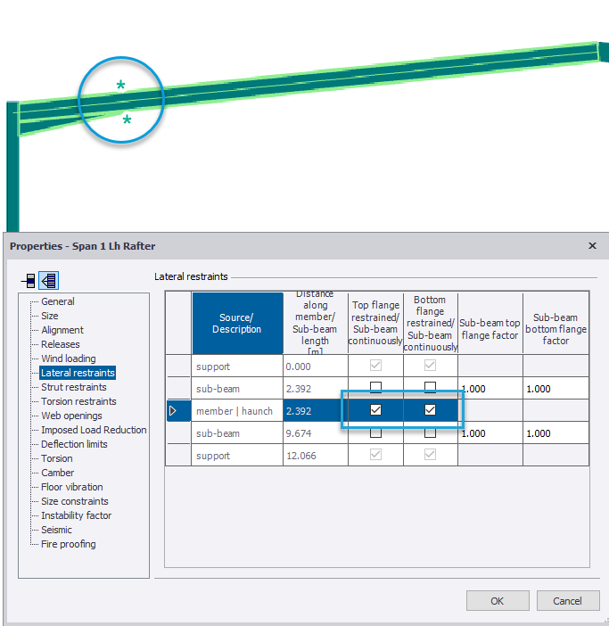
If there are incoming secondary members restraining the sharp end of the haunch, the restraint at this position would previously have been assumed torsional (I.e both top and bottom flanges restrained), this assumption remains unchanged.
This enhancement was already introduced in Tekla Structural Designer 2024 SP4
[TSD-3378] - Steel Columns - improved operation of Properties dialog restraint settings
For steel columns, the operation of the Properties dialog settings for restraints is improved on both the Lateral and Strut restraints pages. Now, when restraints are edited via the override and/ or continuously restrained checkboxes, the sub-stack effective length factor input boxes are automatically updated - either being blanked entirely (for continuously restrained sub-beams/ stacks), or becoming inoperative and grayed-out with a value of 1.000 displayed when no longer applicable. In previous releases, the factor input boxes remained unchanged and operative regardless of edits to the restraint settings, making it unclear which factors were applicable. The operation of the dialog is also enhanced to better reflect the requirements of different regional codes as follows:
-
Eurocode and Indian Regional Codes - account is taken of the presence of Strut Restraints at the location in the determination of a Lateral Restraint (torsional). For columns, all intermediate Lateral Restraints are ignored between full torsional restraints such that all lateral effective length factors except the first after a full torsional restraint are grayed out (working downwards from top to bottom of column).
-
British Standards, USA and Australian Regional Codes - the process ignores all Strut Restraints when determining Lateral Restraints (torsional) as there is no requirement for either a major or a minor strut restraint at the same location as Lateral Restraints on both flanges in order to define the full torsional restraint. Lateral restraints to Flange A and Flange C are considered as switches for setting restraints On/ Off and graying behavior of effective length factors acts appropriate to these settings, with only intermediate lateral restraints on a flange in bending tension being ignored between full torsional restraints.
This enhancement was already introduced in Tekla Structural Designer 2024 SP3
[TSD-14140] - Composite Beam Design - new max and min bar size autodesign control
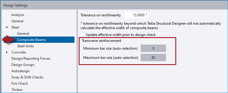
New settings to control the minimum and maximum transverse reinforcement size considered during autodesign have been added to the Design Settings dialog for Steel > Composite beams, as shown in the picture below. This becomes applicable when the option to auto-select transverse reinforcement is enabled in the composite steel beam properties. This applies to the Eurocode and BS Regional codes (all countries).
This enhancement was already introduced in Tekla Structural Designer 2024 SP2
Design - Eurocode
[TSD-16211] - Connection Resistance check for EQU combinations
Following customer requests, the check for simple connection resistance is now performed for EQU combinations (as is steel member design) when these are present and active.
This enhancement was already introduced in Tekla Structural Designer 2024 SP2
[TSD-15743] - RC Beam Design - equation for additional link reinforcement for torsion adjusted
The equation to calculate the area of required link reinforcement over spacing for torsion in the design of RC beams to EN 1992-1-1 has been amended in order to remove some conservatism, in line with general guidance. Previously the equation included a 0.9 factor in the denominator - this is now removed.
This enhancement was already introduced in Tekla Structural Designer 2024 SP1
Design - USA regional code
[TSD-14558] - Staged Construction Analysis enabled for steel design for the United States Regional Code
The scope of Staged Construction Analysis has been expanded to include steel design to the United States AISC Regional Code.
This enhancement was already introduced in Tekla Structural Designer 2024 SP2
Seismic Analysis & Design Enhancements
The following improvements have been made to the settings and processes for Seismic Analysis & Design:
-
TIR Calculation and reporting enhancements
-
[TSD-16397] - Improved Accuracy
Previously, the calculation of TIR considered displacements of the accidental torsion load cases acting in isolation and in both directions for orthogonal combinations, which could produce an over-large TIR value. The method no longer considers these displacements,so that it now produces a more accurate TIR value.
-
[TSD-16407] - Improved operation and reporting
Previously TIR was not calculated or updated when the Calculate Seismic Drift at "Every Column/Wall Stack" option was selected on the final page of the Seismic Wizard. TIR is now calculated with this setting selected. Since the TIR calculation uses the results of the Seismic Drift check, it is not calculated when the "Skip Seismic Drift Checks" option is enabled in Seismic Wizard. To make this more clear when this is the case, the Seismic Design Report now states “Torsional Irregularity Ratio not calculated - drift checks off”.
-
-
[TSD-16393] - Orthogonal Combinations no longer forced with SDC = C and Plan Irregularity 1 for ASCE 7-22
Previously, for SDC = C and Plan Irregularity 1 specified in the Seismic Wizard, the generation of orthogonal seismic combinations was automatically enforced. However, per ASCE 7-22 Section 12.5.3, the independent directional procedure is allowed for any structure with a SDC = C except for structures with a Plan irregularity type 5. Hence for SDC = C, the generation of orthogonal seismic combinations is now only enforced when Plan irregularity 5 is specified. Note that when this is not the case, the use of orthogonal seismic combinations can still be optionally enabled via the check-box option on the Structure Irregularities page of the Seismic Wizard.
-
[TSD-16319, 16388] - Seismic Torsion Renamed to Seismic Accidental Torsion
The “Seismic Torsion” load cases have been renamed “Seismic Accidental Torsion” to make it more clear that these are the accidental torsion moments Mta deriving from section 12.8.4.2 of ASCE7.
In addition, in the Seismic Design Report when they are reported the Amplified Accidental Torsion result tables now use the term “Mta” in place of the previous “Mt” in the torsion value column header.
These enhancements were already introduced in Tekla Structural Designer 2024 SP2
[TSD-13460, 16042] - Composite beams - Connector Resistance warning for deformation capacity
For the AISC 360/ 341 2016 code year for beams > 30 ft span with degree of shear connection < 50%, the Connector Resistance check warning for stud connector deformation capacity per the Commentary on I3.2d.1 is changed from being based on the average shear connector group spacing of 12in as suggested, to being based on the alternative of the average nominal shear connector capacity (in terms of kpf). Where the warning could previously be frequently issued this should no longer be the case.
This enhancement was already introduced in Tekla Structural Designer 2024 SP1
