New Show/Alter State Attribute: Effective Lengths and Factors
In the 2024 Service Pack 3 release, we have added a powerful and comprehensive "Effective Lengths & Factors" attribute to Review View > Show/Alter State. This feature enables rapid graphical review and editing of Effective length settings for steel columns and beams and concrete columns and walls and aids in giving the engineer full confidence that this critical design parameter is as intended/ required. This enhancement is applicable to all Regional Design Codes.
For more details about this feature, see the Help Topic Effective Lengths and Factors - review and copy and the video Show/Alter State: Effective Length Settings.
Overview of Options
When the Show/Alter State “Effective Length & Factors” attribute is selected in the Properties Window, the information then displayed is controlled by the Options: "Mode", "Entity type", "Variant" and "Restraint type/ Direction".
-
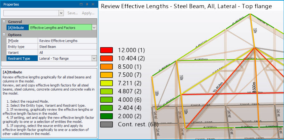
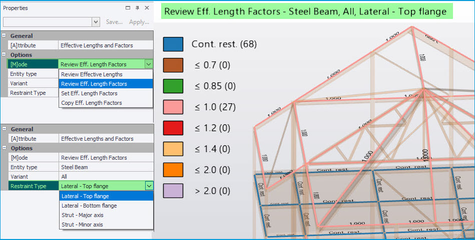
Mode - the initial Mode is “Review Effective Lengths”, as shown in the picture above. This displays the actual effective length in terms of length units and is applicable only to Steel beams and columns. The unrestrained length value and units are displayed graphically along the member, at its middle, and members are color coded in automated ranges given by the legend. “Cont. rest.” text is displayed and the gray legend color is assigned for lengths to which continuous restraint is applied - for example for the “Lateral - Top flange” Restraint Type shown in the picture above. Note the number of entities within a particular range/ with a particular setting is displayed in brackets in the legend e.g. (68) giving the number of beams in the view with continuous top flange restraint.
The other available Modes in the [M]ode drop list as shown below all relate to Effective Length Factors and are; “Review Effective Length Factors”, “Set Effective Length Factors” and “Copy Effective Length Factors”. See below for more on these.
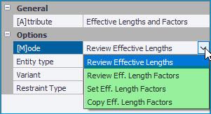
-
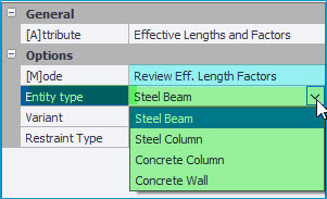
Entity type - this sets the view information for the selected Entity type you wish to work with. The types available are governed by the selected Mode - e.g. when the Mode is set to “Review Effective Lengths”, only Steel Beam and Steel Column are available in the Entity type list as shown below left. With the Mode set to “Review Eff. Length Factors” note that all the available Entity types are listed for selection as shown below right.
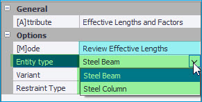
-
Variant - to make it easier to focus on the entities and settings you want to work with, the view information can also be filtered by using the “Variant” drop list. This lists all the variants of the selected Entity type contained in the model and is only displayed when the model actually contains entities of the selected type.
-
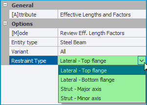
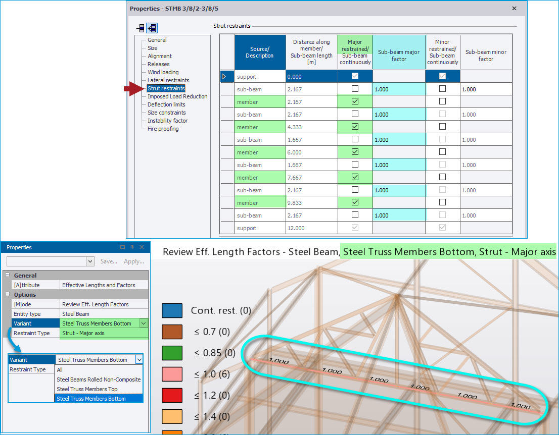
Restraint Type - for steel beams and columns you select the “Restraint Type” you want to work with from the options available. The options listed depend on the selected Entity type - as shown below for the Entity type Steel Beam they are ; Lateral - Top and Bottom flange and Strut - Major and Minor axis (for the USA Regional Code a “Torsion” option is also included related to the Comp Kz factor). The view then updates to display this information accordingly with the selected options being shown in the view title text, as shown in the larger picture above.
Review Eff. Length Factors Mode - steel beams and columns
To see information about Effective Length factors, switch the Mode to the “Review Eff. Length Factors” option - the view values, color coding and legend then display the effective length factor values throughout the model for the specified Entity type, Variant and Restraint Type as shown in the picture below.
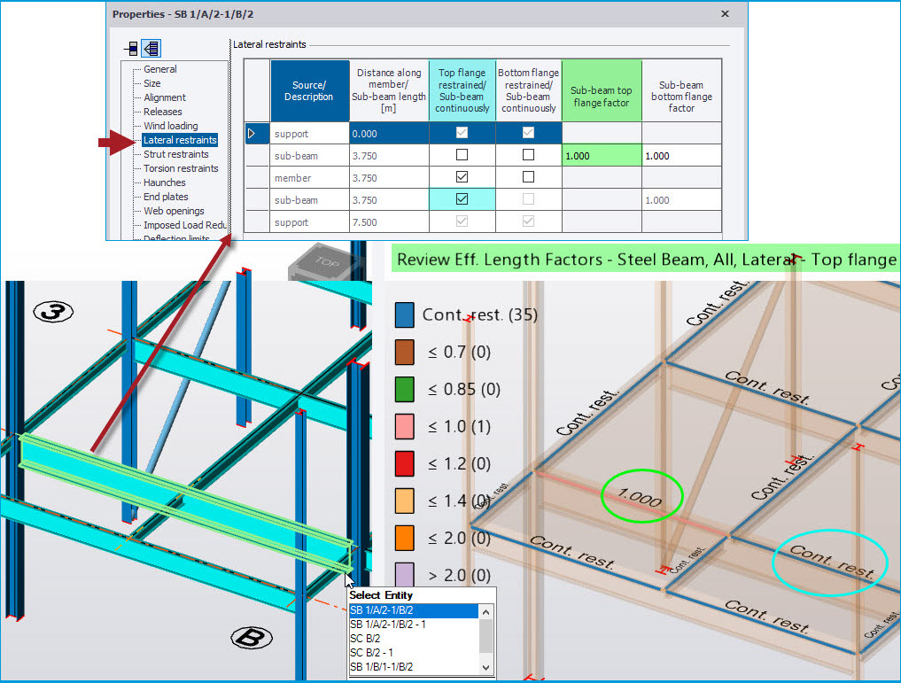
For steel beams and columns, the Restraint Types and the displayed values correspond to those in the individual member properties dialog on the “Lateral restraints” and “Strut Restraints” pages.
For example as show in the picture below, for a steel beam for the Lateral - Top flange restraints of a primary beam supporting a secondary beam- the new Review view of effective length factors shows the individual settings/ factors of the two sub-beam lengths - produced by the restraint of the secondary beam - one length being unrestrained with a factor of 1.0 and the other continuously restrained in this case.
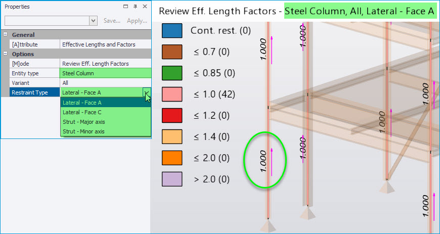
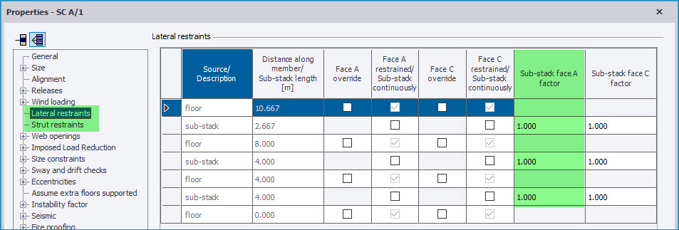
For Steel Columns the Restraint Types are; Lateral - Face A/ Face C and Strut - Major/ Minor axis, as shown in the picture below. Again as for steel beams, the Restraint Types and the view displayed values correspond to those in the individual member properties dialog on the “Lateral restraints” and “Strut Restraints” pages as shown below.
Note that in this view the member direction arrow for columns is also automatically shown - the arrow being drawn on Face A of columns so this can readily be identified.
Note that the new Review View of Effective Lengths and factors for steel beams and columns also applies to the members of Portal Frames - both their rafters and columns. Hence this now makes possible graphical review and editing of continuous restraint settings for Portal Frame members, which was not previously possible using the existing Review View > Restraints command.
Review Eff. Length Factors Mode - concrete columns & walls
To see information about concrete column & wall effective length factors, select either of these as the Entity type after switching the Mode to the “Review Eff. Length Factors”. The view values, color coding and legend then display the effective length factor values throughout the model for the specified Entity type, Variant and Direction.
For concrete column and wall entities the “Direction” setting replaces “Restraint Type” of steel members, and has options of Direction 1/2 for columns and Major/ Minor for walls.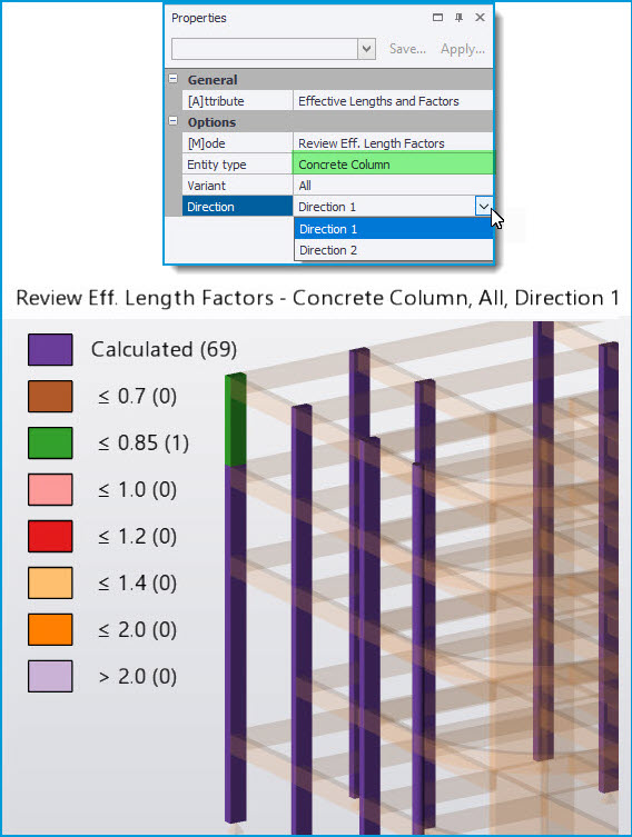
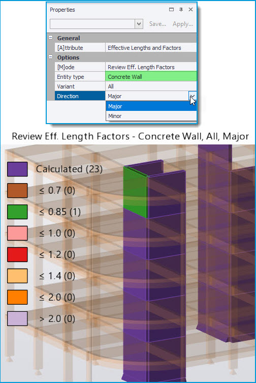
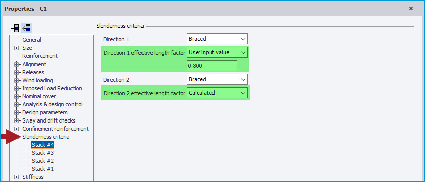
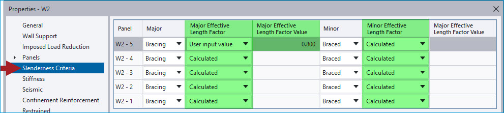
For Concrete Columns and Walls, the displayed settings/ values correspond to those in the individual member properties dialog on the “Slenderness criteria” pages as shown in the pictures below of the properties of both a column and wall. The column stacks/ wall panels in the view will be color coded for either “Calculated” for those set to automatically calculate their effective length (the default setting) or in the automatic numerical legend color ranges for those with a “User input value” of effective length factor, as shown in the picture above.
Set Effective Length Factors Mode
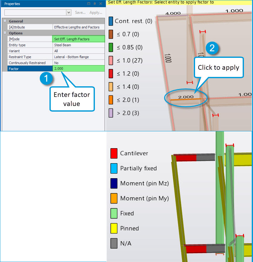
Effective length factors can be set directly using the “Set Eff. Length Factors” Mode. For example the engineer may wish to set longer lateral effective length factors for some steel beams to account for such conditions as cantilevers and/ or destabilizing loads (e.g. when designing to the Eurocode following the guidance of SCI AD-408) as shown in the picture below.
To apply effective length factors directly with the mode set to “Set Eff. Length Factors”, simply set the Restraint type (or Direction for concrete columns/ walls) to the desired option and “Continuously Restrained” = No then 1) enter the factor value in the Properties Window and 2) select an entity (beam length/ column stack/ wall panel) with the cursor to apply - multiple lengths/ stacks/ panels can be selected for application in the usual manner (see Select entities for guidance on making multiple selections).
For steel beams and columns you can also use Set Mode to directly set “Continuously Restrained” = Yes, for any of the Restraint Types, by selecting this option in the Properties Window (in which case the Factor row is not displayed) then selecting entities to apply this setting to in the view.
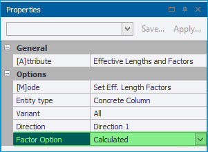
Similarly for concrete columns and walls the stack/ panel “Factor Option” can be directly set to “Calculated” rather than a directly specified value for a selected Direction, as shown in the picture below.
Copy Effective Length Factors Mode
Effective length factors can also be copied using the “Copy Eff. Length Factors” Mode. This works as follows:
-
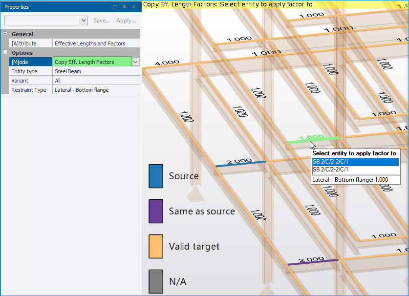
With this mode selected and the desired Entity type and Restraint Type/ Direction set, you first select the entity to copy the factor from.
-
At this point the appropriate entities in the scene are then color coded and the legend is displayed, as shown in the picture below, to clearly indicate; the source entity, entities with the same value as the source and those with different values which are valid target entities.
-
Then simply select the entity to apply the copied factor to - again multiple lengths/ stacks/ panels can be selected for application in the usual manner.