Tekla Structural Designer 2025 SP2.1
The latest Tekla Structural Designer service pack is available in Trimble Downloads.
Download Tekla Structural Designer
Note:
Service Pack SP2.1 (version is 25.2.1.1) was released on 4th August 2025 to replace SP2 (version 25.2.0.65). This was necessary due to an issue in SP2 that could result in a "File cannot be read" error when opening certain models.
This release will update your Tekla Structural Designer installation to version number 25.2.1.1 and should be installed to ensure optimum function of the program. It includes a number of new features, enhancements and issue resolutions as detailed below.
If you are upgrading from a version earlier than the immediately prior release of 2025 first release (version 25.0.1.45 released March 2025), you can find details of enhancements and fixes for all previous releases in Tekla User Assistance (TUA) via the link below:
Licensing and installation
Licensing
No new license is required for this version.
Client License Service Version - no update is required for this release.
License Server Version - this relates only to perpetual licenses and the Server (Sentinel RMS) license method. Provided your license server has been updated to version 4.3.x or later (incorporating Sentinel RMS 10.0 which added support for Windows 11), no update is required for this release.
Installation
This service pack requires Tekla Structural Designer 2025 first release or later to be installed and will update your current version.
- Integration
Tekla Structures - if you wish to integrate with Tekla Structures for optimum performance you should install both this release and Tekla Structures 2025 (and the most recent Service Pack for this).
Tekla Tedds - for integrated design using Tekla Tedds you should install Tekla Tedds 2025 AND ensure you have installed the latest updates for this. These can be obtained from Trimble Downloads.
Tekla Portal Frame and Connection Designer 25 - if you install this release and use Tekla Portal Frame Designer and/or Tekla Connection Designer you should install Tekla Portal Frame Designer 25 and/or Tekla Connection Designer 25 available from Trimble Downloads.
Autodesk® Revit® - the most recent Tekla Structural Designer Integrator for Autodesk Revit 2025 was released in April 2025. For more information about this see the Tekla Structural Designer Integrator for Autodesk Revit 2025 SP1 Release Notes. The installation for this is available from Trimble Downloads. If you are now using Autodesk Revit 2025, you can install this to perform BIM integration with Tekla Structural Designer.
Supported Revit Versions - the other currently supported Revit versions are: Tekla Structural Designer Integrator for Autodesk Revit 2023 SP2 and Tekla Structural Designer Integrator for Autodesk Revit 2024 SP2. The installation for these are available from Trimble Downloads. If you are performing BIM integration with any of these previous Revit© versions, we recommend you install the latest version of the associated Integrator.
Previous Versions and file compatibility - files from all previous versions can be opened in this release, however note that, once saved, they cannot then be opened in a previous release. If you wish to retain this option we therefore recommend using the File > Save As… option to save a copy of the file in the previous release and retain the original.
Issues with associated bulletins
[TSD-18150] - Incorrect calculation for minimum plate washer thickness (ASD and LRFD)
This issue relates to the design of steel column base plates to US Regional Codes only when welded washer plates are included. The minimum required thickness of the welded washer plate is incorrectly calculated as smaller than it should be, and hence there is the possibility of unconservative design, especially if the default washer plate thickness has been manually reduced. For more information please see Product Bulletin PBTSD-2506-1.
This issue is fixed in in this release.
[TSD-16686] - Steel and precast columns - eccentricity moments incorrectly applied for cantilevering stacks
This issue relates to cantilever steel and precast columns that are unrestrained at their tip. Previously the column connection eccentricity moments were incorrectly distributed. For more information please see Product Bulletin PBTSD-2411-1.
This issue is fixed in this release.
Highlights
In this section we give details of some of the significant new features included in this release. These are intended to give a broad overview of their function and workflow and significant changes in operation/ behavior.
Enhancements and fixes
General & modeling
General performance and stability improvements
A number of additional fixes which are not detailed explicitly here are also made in this release to improve general performance and stability.
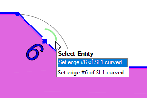
[TSD-18124] - Curved slab edges
New options have been added to simplify the creation or removal of curved slab edges (both convex and concave) in 2D views.
Click on the new curved symbol next to the straight edge to start the curve edge creation procedure.
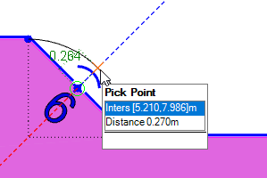
You will be prompted to pick a point to define the crown of the curve - note that snapping is supported.
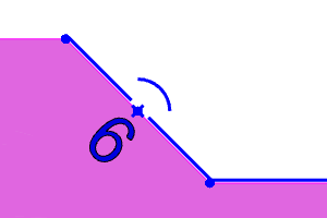
Once an edge is curved, the symbol changes to a straight line.
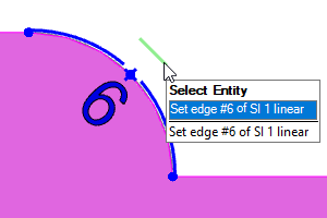
If you click on the straight line symbol, the edge returns to straight. Or you can click on the edge itself to adjust the curve (again snapping is supported).
In addition to the above, in a further small change the "new node" symbol on any edge has been changed from a dot to a + to differentiate it from the existing nodes at the ends of existing edges.
An example which makes use of a dxf shadow to create the curved edges is illustrated below.
For further details, see the help topic: Work with curved slab edges.
[TSD-18041] - Amend orientation of sloped plane views
In previous releases sloped plane views were always orientated according to the up slope direction. This could be confusing if multiple planes in the model sloped in different directions.
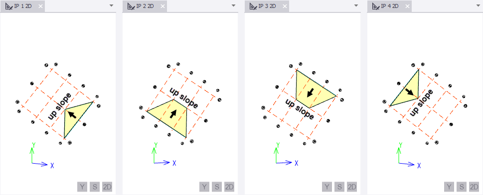
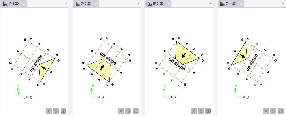
To illustrate, consider the following model in which there are 4 sloped planes, (none of which are aligned to the global axes).
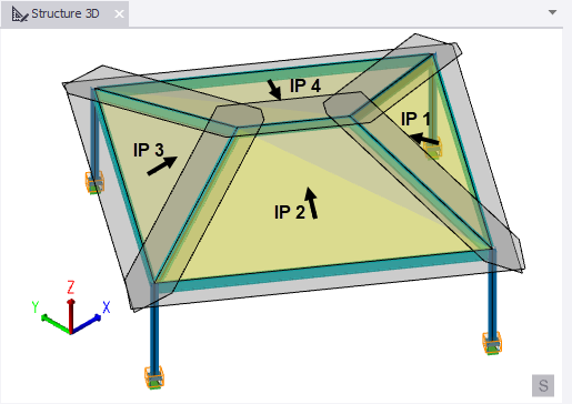
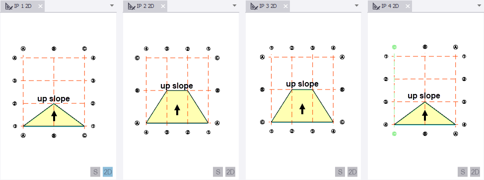
Previously, when sloped plane views were displayed for this model they would not be aligned to the global axes. This is because sloped plane views would always adopt an Up slope upward orientation, as shown below:
Tekla Structural Designer 2025 SP2 introduces new functionality to improve sloped plane orientation understanding and modification. When opening a model, the existing orientation is retained, but you can now better comprehend it relative to the global axes, and change it if required.
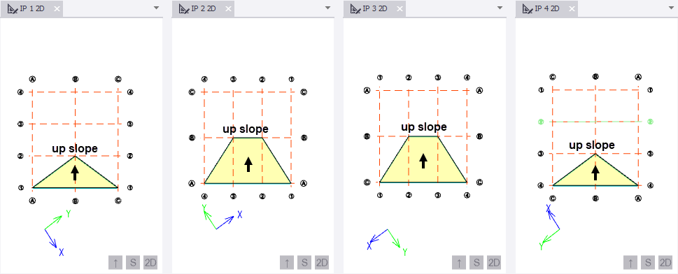
A Global X and Y axes symbol make it easier for you to visualise the current orientation
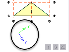
An orientation button at the bottom right of the view describes the current orientation and allows you to change it. (In the above view the button text,
 , tells you the current orientation is Up slope upward.)
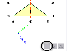
Clicking the button toggles between Up slope upward and two new orientations.
The two new orientations are:
Global Y direction upward

In this orientation the Global Y axis is drawn vertically upwards and the Global X axis is realigned accordingly.
Global X direction to the right

In this orientation the Global X axis is drawn to the right and the Global Y axis is realigned accordingly.
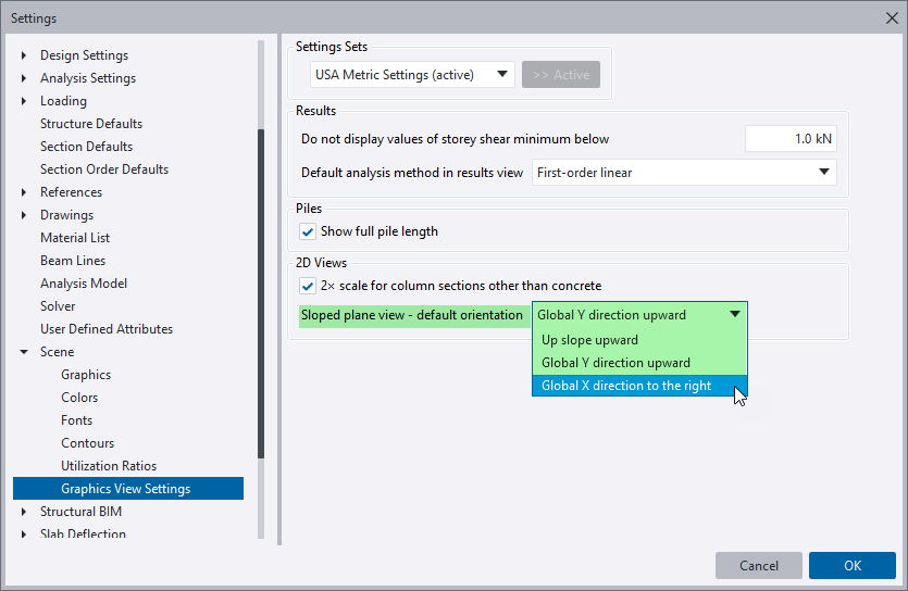
On the Scene > Graphics View Settings page in the Settings dialog, you can specify the orientation for newly created views using the Sloped plane view - default orientation setting. (This global setting gets copied to the Graphics View Settings page in Model Settings should you want to change the default for the currently open model.)
[TSD-18246] - Orientation of concrete beams modelled on a sloping plane
Previously when concrete beams and joists/joist girders were placed in a sloped plane they were orientated in the same way as beams of other materials, so that if the rotation angle was 0 degrees the minor (z) axis would be normal to the plane.
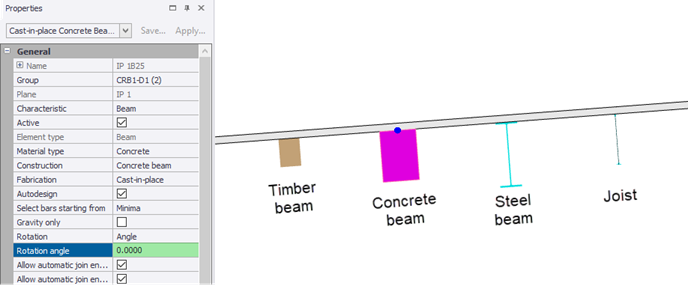
In response to customer feedback, the default behavior has been amended so that for concrete beams and joists/joist girders only, by default the minor (z) axis is now vertical (i.e. aligned with global Z). To facilitate this a new Use global reference plane property has been introduced.
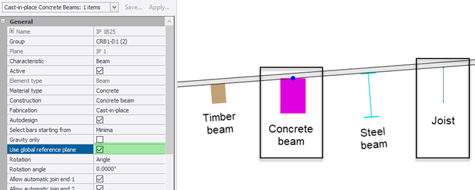
The Use global reference plane property is displayed once the member has been placed, and only then if the plane in which the member has been defined is a sloped plane.
By default Use global reference plane is selected for concrete beams, joists and joist girders, but unselected for beams in other materials. You can toggle the selection to have the member rotation measured with respect to the global plane or local sloping plane as you require.
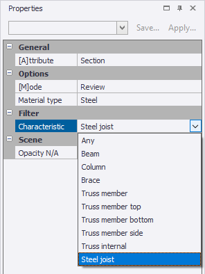
[TSD-17978] - Show / alter State - Option of Steel Joists
When Section/Material Grade is selected on the Review ribbon, in the properties under Characteristic there is now a “Steel joist" option. Previously, steel joists were only included for section/material grade review views when "Any" was selected under Characteristic.
Interoperability
Remoting API Enhancements
There have been some enhancements to the Open API with this release - for information about these see the Tekla Structural Designer 2025 Open API Release Notes page.
Design - General
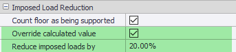
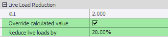
[TSD-9791] - Live/Imposed load reductions - User override for members calculated automatically
A user override option (Override calculated value) has been added for the members in which imposed/live load reductions take place automatically.
For EC, BS, IS and AS codes this option allows the user to specify their own percentage of load reduction for columns and walls.
For US code this option is available for beam members in addition to columns and walls.
Design - ACI/AISC United States
[TSD-18299] - Concrete wall design - tie diameter value used incorrectly when no ties exist in mid-zones
Corrected an issue where only the tie bars in mid zones of RC walls (whether applied or not) were considered for the maximum tie bar spacing calculation. End zone tie bars were ignored. Depending on the parameters input, although unlikely, this had the potential to result in an unconservative maximum tie bar spacing limit.
[TSD-18293] - Masonry walls - Process error performing model updates
An issue has been fixed where the spacing of the reinforcement in masonry walls was not adequately adjusted when the height of the wall span was updated. This would in turn result in errors during the analysis process.
The adjustment of the spacing is now enforced and a model update has been introduced so that the inadequate spacing retained due to the mentioned issue is now correctly updated.
[TSD-10200] - Composite beam design - allow shear connectors smaller than 3/4" dia.
A broader range of stud diameters is now allowed for the US (1/2" to 1").
Note that Tekla Structural Designer does not check the dimensional requirements for the studs themselves, for example to the 'User Note Table' in AISC 360-16 I8.3.
Design - Eurocode
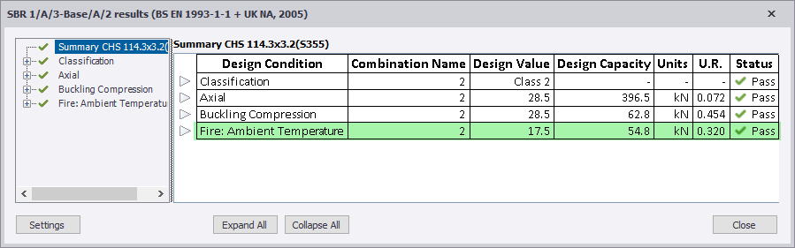
[TSD-17357] - Fire design - steel brace ambient utilisation
The ambient temperature calculations can now be included in the design checks for braces by selecting Ambient temperature utilization located under Fire proofing in brace properties.
The critical ratio is then reported in the design summary table.
Drawings
[TSD-18145] - Snow drift missing from loading plan drawings
Previously, when you created a Loading Plan drawing for a snow loadcase, the drawing included the balanced snow loading, but did not include any drift loads.
This is now corrected.
Note: The number in brackets before an item denotes an internal reference number. This can be quoted to your local Support Department should further information on an item be required.