Release notes: Tekla Structural Designer 2024 SP3
Note:
This Service Pack was re-released on 28th November 2024 and the new version is 24.3.1.0 (was 24.3.0.104).
This release will update your Tekla Structural Designer installation to the above version number and should be installed to ensure optimum function of the program. It includes a number of new features, enhancements and issue resolutions as detailed below.
If you are upgrading from a version earlier than the immediately prior release of 2024 SP2 (version 24.2.0.88 released Sept 2024), you can find details of requirements, enhancements and fixes for all previous releases in Tekla User Assistance (TUA) and the Download Service via the links below:
Licensing & installation
Licensing
-
No new license is required for this version.
-
Client License Service Version - no update is required for this release.
-
License Server Version - this relates only to perpetual licenses and the Server (Sentinel RMS) license method. Provided your license server has been updated to version 4.3.x or later (incorporating Sentinel RMS 10.0 which added support for Windows 11), no update is required for this release.
Installation
-
This service pack requires Tekla Structural Designer 2024 first release or later to be installed and will update your current version.
-
Previous Versions and file compatibility - files from all previous versions can be opened in this release, however note that, once saved, they cannot then be opened in a previous release. If you wish to retain this option we therefore recommend using the File > Save As… option to save a copy of the file in the previous release and retain the original.
Integration
- Tekla Structures - if you wish to integrate with Tekla Structures for optimum performance you should install both this release and Tekla Structures 2024 (and the most recent Service Pack for this).
-
Tekla Tedds - to use Design using Tekla Tedds with this release, you should install Tekla Tedds 2024 AND ensure you have installed all the latest updates for this. These can be obtained from the Download Service.
-
Tekla Portal Frame and Connection Designer - if you install this release and use Tekla Portal Frame Designer and/or Tekla Connection Designer you MUST install Tekla Portal Frame Designer 24 and/or Tekla Connection Designer 24 (released in Mar 2024) available from the Download Service.
-
Autodesk Revit© - the Tekla Structural Designer Integrator for Autodesk Revit© 2024 was released in September 2023. For more information about this see the Tekla Structural Designer Integrator for Autodesk Revit 2025© Release Notes. The installation for this is available from the Download Service. If you are now using Autodesk Revit© 2025, you can install this to perform BIM integration with Tekla Structural Designer.
-
Supported Revit Versions - the other currently supported Revit© versions are:
Tekla Structural Designer Integrator for Autodesk Revit 2022© SP1, Tekla Structural Designer Integrator for Autodesk Revit 2023© SP2 and Tekla Structural Designer Integrator for Autodesk Revit 2024© SP1. The installation for these are available from the Download Service. If you are performing BIM integration with any of these previous Revit© versions, we recommend you install the latest version of the associated Integrator.
-
Issues with associated bulletins
-
[TSD-14892, 16803, 16986] - Incorrect seismic, notional and minimum lateral loads for some configurations of single bracing
These issues relate to an error in the calculations performed locally at the node formed where one or more single braces attach to a beam within its span. The following calculations were affected: Seismic weight/ mass and forces, notional loads, minimum lateral loads, storey forces/shears. This situation would occur for example when modeling eccentric bracing. Note that the issue did NOT occur for A or V Brace patterns. For more information please see Product Bulletin PBTSD-2403-01.
-
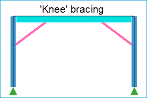
This issue was fixed for the majority of such brace configurations in Tekla Structural Designer 2024 (version 24.0.1.45 released in Mar 2024). However it was subsequently found that an issue still existed for a less common arrangement of bracing, often termed ‘knee’ bracing as illustrated in the picture below. For this bracing configuration the loads were still incorrect and generally overestimated following the fix in release 2024 (and underestimated prior to this). This is fixed in this release.
- As part of this fix, an issue with incorrect lateral
deflections of beams to which these seismic, notional or minimum lateral
loads were applied (e.g. at the connection of ‘knee’ braces to beams) is
also fixed in this release.
-
-
[TSD-17015] - Masonry Wall design using Tekla Tedds - potentially unconservative design when using metric units
The design of masonry walls to US regional codes, and only for models created using metric units, could result in smaller grout or vertical reinforcement spacing than was initially specified, potentially yielding unconservative designs. For more information please see Product Bulletin PBTSD-2410-1.
-
This issue is fixed in this release.
-
Highlights
In this section we give details of significant new features included in this release. These are intended to give a broad overview of their function and workflow and significant changes in operation/ behavior - please refer to the associated Release 2024 SP3 Help topics for full details.
Other enhancements and fixes
General & modeling
-
General performance and stability improvements
A number of additional fixes which are not detailed explicitly here are also made in this release to improve general performance and stability. An example of this is given directly below:
-
[TSD-16959] - Meshing and diaphragms process error fixed
A Meshing and diaphragms process error preventing the completion of analysis, which could occur for models with piled mats supporting columns - where one or more piles were within the area of a column - is fixed in this release.
-
-
Improved View Information for Column and Walls
The following improvements are made in this release to information displayed in views for column and wall entities:
-
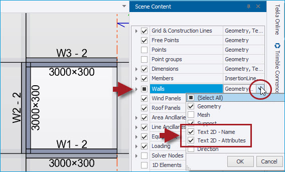
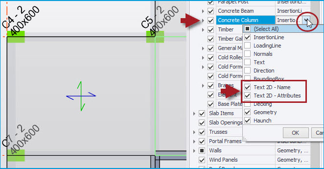
[TSD-15394] - New View Text 2D for Name and Attributes
The Name (default or user name) and/ or Attributes (dimensions/ thickness and (steel) grade) of columns and walls (of all materials/ types) can now be displayed in 2D plane views. As shown in the pictures below, the viewing of this new text is enabled via the Scene Content checkboxes for “Text 2D- Name” and “Text 2D- Attribute” for walls and columns.
-
-
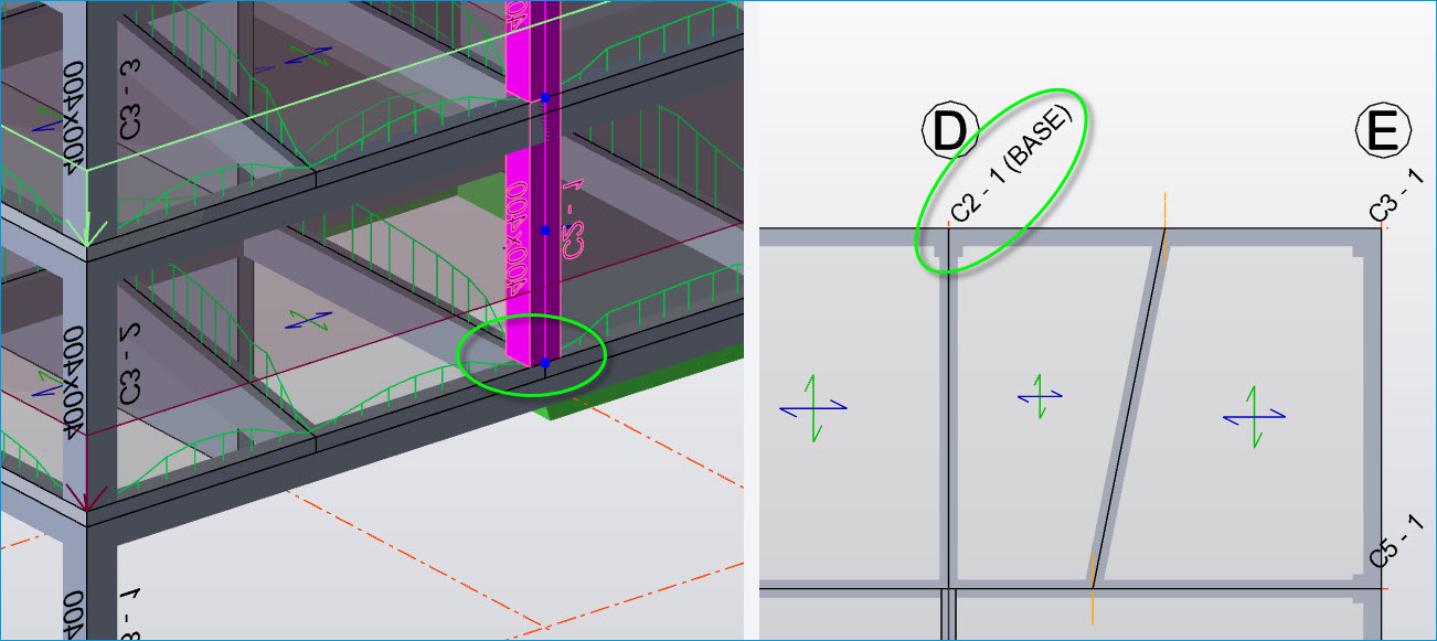
[TSD-16901] - Name text Improved to distinguish columns and walls terminating without direct support
The base levels of columns and walls that terminate without a direct support are now distinguished in 2D views by the text “(BASE)” being appended to their reference, as illustrated in the picture below. The purpose of this is to highlight transfer locations (columns or walls supported by beams or slabs). This can also highlight unintentional mis-modeling, e.g. separate columns or walls stacked one on top of the other.
-
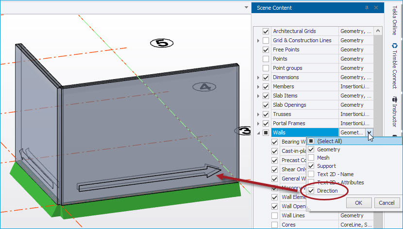
[TSD-16876] - Wall Panels - New Direction Arrow
A new Scene Content option to display the direction of walls is added in this release - when this is enabled, an arrow is displayed in the view on each wall panel showing its positive direction i.e. that from the start insertion point to the end insertion point, as shown in the picture below. This assists in editing models and understanding results etc.
-
[TSD-16885] - Wall Panels - corrected length information
Previously the Length information shown in a wall panel tooltip reported the length between the two insertion points used to locate the wall. This is changed to show the real physical length of the wall (as used in design).
-
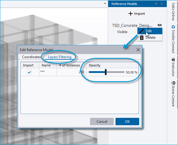
[TSD-16024] - Reference models - Transparency settings
For the recently added Reference Models (introduced in release 2024) this release adds new control over their transparency. New individual Opacity controls are provided for each layer on the Layers Filtering page of the Edit Reference Model dialog when importing a new reference model. For previously loaded models, the same Edit Reference Model dialog is accessed via the Edit context menu option on right-clicking over a model in the Reference Models Window list, as shown in the picture below.
-
To help with the performance of rendering large models, opacity defaults to 50% (128) for layers with a reasonable number of elements but is kept at 100% (255) for layers with a significantly large number of elements.
-
-
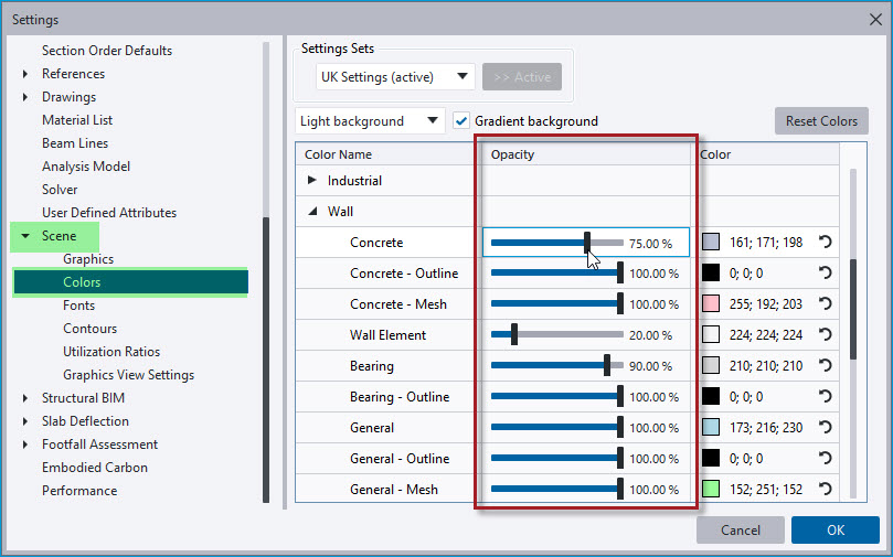
[TSD-16849] - Scene Settings - improved operation of Opacity settings
All previous releases of Tekla Structural Designer have featured opacity controls in Global Settings > Scene > Colors in the form of sliders to adjust the opacity levels of entities in graphical views, as shown in the picture below. More recently these sliders have also been implemented for layers when importing reference models. These controls are improved in this release to make them simpler and more practical to use as follows:
-
The slider range is now between 5% and 100%, in place of the previous 0 to 255.
-
When moved with the cursor, the slider snaps at 5% intervals and existing levels are rounded to the nearest 5%.
-
Cursor clicks on the slider track now move the slider by 25% instead of 1% at a time.
-
Loading
-
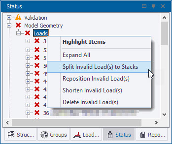
[TSD-14002] - Improved handling of invalid loads on columns
In some rare circumstances, invalid member loads can be produced during the modeling process, producing Model Geometry > Loads validation errors, as shown in the picture below. These must be resolved before analysis or design can be continued. Expanding on the options for this circumstance, a new option to 'Split invalid load(s) to stacks' is added to the list of options to manage invalid loads, in the context menu of invalid loading errors in the status tree. This new option applies to UDL loading applied to columns that can become invalid when the column is subsequently split at a position along the length where the load is applied. Rather than having to delete the invalid load as previously, it enables the load to be automatically reinstated between the same original points, albeit now split at the same position as the split in the column stack.
Interoperability
-
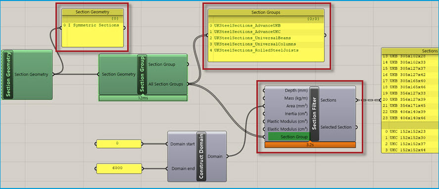
[TSD-16751] - Grasshopper Live Link enhancements for working with sections
The Grasshopper - Tekla Structural Designer Live Link is enhanced in this release to improve selection and filtering of sections with two new components and one updated component as follows.
-
New Section Geometry component - this outputs the selected Section Geometry from the list of available section geometries.
-
New Section Group component - this takes the Section Geometry as an input and will output either a selected section group, or all available section groups for the selected geometry.
-
Updated Section Filter component - this has been adjusted so that the user no longer specifies the Section Geometry and Group from a dropdown selection. Instead, the Section Group is input to the component.
-
-
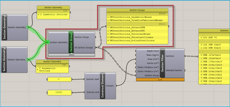
For the new inputs to the Section Group and Section Filter, it is now possible to combine different outputs from the upstream components to enable multiple selections to be included in the filter as shown in the picture below.
-
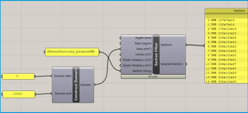
The main intention is to use the output of the upstream components to the new inputs as illustrated above. However, as shown below, it is also possible to provide a text input to the Section Geometry input on the Section Group component, and also the Section Group component on the Section Filter component.
-
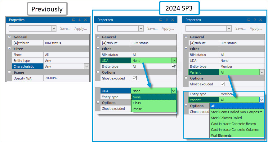
[TSD-15551] - Review View - Show/Alter State BIM Status enhancements
The functionality of Show/Alter State BIM Status has been enhanced to allow for the displayed BIM Status to be filtered according to the UDA values (for example phases) that have been assigned to entities via the new “UDA” control, as shown in the picture below.
-
The existing filter controls are also improved with the previous“Characteristic” setting being replaced by “Variant” as shown below right. The “Variant” option is only displayed when an Entity type - such as “Member” as shown - is selected, with the drop down options list being automatically populated with only those variants contained in the model.
-
Validation
-
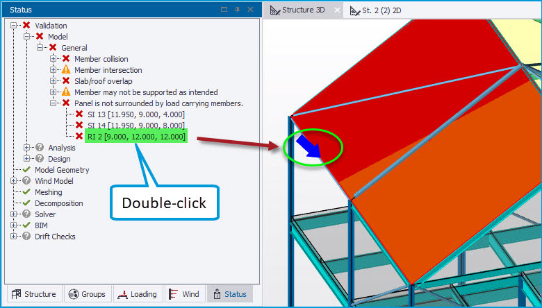
[TSD-15229] - Panels - improved location of spanning issue indicator arrow
For one-way spanning panels with the validation error "Panel is not surrounded by load carrying members”, the location of the blue arrow indicating the problem, displayed in the view on double-clicking the validation error, is improved in this release. Previously it would point to the panel but not to the specific coordinates indicated in the validation error, which could make it difficult to locate the cause of the issue. The validation error coordinates are now used to determine the placement of the location arrow, allowing the user to more quickly locate the problem in the view and take action - e.g. in the example below the arrow now points to the specific edge of the roof panel where the problem lies (that where it spans towards a brace member which does not support decomposed loads)
-
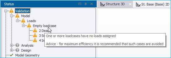
[TSD-16687] - Loading - new validation for empty load cases
New validation checks and associated warnings have been added in this release for Empty loadcases. As shown in the picture below, this issues an “Empty loadcase” warning in the Status > Validation tree with an explanatory tooltip and listing any loadcases with no loading defined within them. An option is then provided via the right-click context menu to delete any/ all of the listed loadcases. The new validation skips the "Self weight - excluding slabs" and "Slab self weight" cases when their “Calc Automatically” setting is enabled (the default) but will list them when this is disabled and they are otherwise empty.
Analysis & results
-
[TSD-16479] - 2D Elements - meshing process updated
The (fully automatic) process of producing the mesh of 2D elements for panels (slabs, walls and semi-rigid diaphragms) is updated to a new version in this release. The tools used for the meshing process are periodically updated to improve performance in terms of for example efficiency and 2D element quality.-
While there are no changes whatsoever to the meshing constraints and controls (for more about these see Adjust global slab mesh properties , Adjust the wall mesh parameters and Slab meshing controls), the updated process may result in very slight changes in the mesh configuration (2D element size, shape and density etc). With the essentially approximate nature of FEM, this may produce correspondingly slight changes in analysis results - and hence design which uses these - when compared to previous releases. However, it is expected that any such changes will generally be very minor and all our internal testing has shown this to be the case.
-
Design - general
-
[TSD-3378] - Steel Columns - improved operation of Properties dialog restraint settings
For steel columns, the operation of the Properties dialog settings for restraints is improved in this release on both the Lateral and Strut restraints pages. Now, when restraints are edited via the override and/ or continuously restrained checkboxes, the sub-stack effective length factor input boxes are automatically updated accordingly - either being blanked entirely (for continuously restrained sub-beams/ stacks), or becoming inoperative and grayed-out with a value of 1.000 displayed when no longer applicable. In previous releases, the factor input boxes remained unchanged and operative regardless of edits to the restraint settings, making it unclear which factors were applicable. The operation of the dialog is also enhanced to better reflect the requirements of different regional codes as follows:
-
Eurocode and Indian Regional Codes - account is taken of the presence of Strut Restraints at the location in the determination of a Lateral Restraint (torsional). For columns, all intermediate Lateral Restraints are ignored between full torsional restraints such that all lateral effective length factors except the first after a full torsional restraint are grayed out (working downwards from top to bottom of column).
-
British Standards, USA and Australian Regional Codes - the process ignores all Strut Restraints when determining Lateral Restraints (torsional) as there is no requirement for either a major or a minor strut restraint at the same location as Lateral Restraints on both flanges in order to define the full torsional restraint. Lateral restraints to Flange A and Flange C are considered as switches for setting restraints On/ Off and graying behavior of effective length factors acts appropriate to these settings, with only intermediate lateral restraints on a flange in bending tension being ignored between full torsional restraints.
-
Note: The number in brackets
before an item denotes an internal reference number. This can be quoted to
your local Support Department should further information on an item be
required.