Print to a PDF file, plot file (.plt) or printer
You can print drawings and selected drawing areas to PDF files or to plot files (.plt) to be sent to a plotter or printer, or print drawings on a printer. You can also modify the output line colors and line widths. You can print to a single printer or to multiple printers, or print one drawing to multiple sheets.
Print a drawing
-
On the File menu, click .
This opens the Print Drawings dialog and Document manager.
You can also start printing in the following ways:
- In Document manager, select the drawings, right-click, and select Print, or click the Print
 button.
The order of drawings matches the order they appeared in Document manager at the point in time when the Print Drawings dialog was opened.
- When a drawing is open, select .
- Press Shift+P on the keyboard.
- In Document manager, select the drawings, right-click, and select Print, or click the Print
-
Load the desired printing
settings from the settings list.
When you load the printing settings, the Save button remains disabled. Once you make some changes in the printing settings, the name of the settings file will be displayed in italics and get an asterisk at the end. The Save button will be enabled once you have modified the settings.

You can also give the settings a new name. For more information about the printing settings, see Printing settings files and search order.
-
To show a preview of the
drawing, click Click here to load a preview in the preview area.
-
The drawing preview is always up to date. Check the preview whenever you change the printing settings.
-
Use the mouse wheel to zoom in the preview. You can also zoom into areas of interest. If the preview gets unclear when you are zooming, maximizing the window might help.
-
The preview also supports panning with the middle mouse button.
-
If you want to preview with precision, place the printing dialog so that you can see the current drawing and ensure that you have activated the Printer line widths switch in .
-
If you have selected to print several drawings, the drawings are shown one by one in the preview. Use Next and Previous to scroll through the set of selected drawings.

-
-
If you have selected drawings that need numbering or updating, a dialog
is displayed, and you can select how to proceed:
Note: You cannot update or number locked drawings.
- Print only up-to-date drawings (recommended)
- Number and update before printing the drawings
- Print drawings without updating
- To cancel the whole process, click Cancel.

-
Click Print.
A summary is displayed showing you the printing result and a list of drawings that need attention.

Define printing settings
Settings on Options tab
| Setting | Options and description |
|---|---|
|
File location |
Enter the location for the PDF file or plot file, or use Browse... to browse to the folder. The \Plotfiles folder under the model folder is the default value. This option is only available if you have selected PDF file or Plot file. |
| Printer or plotter | Select the printer or plotter. Click Properties... to adjust printer properties. |
|
Include revision mark to file name |
Add the mark of the latest revision of the printed drawing to the print file name. Revision number is used by default. If you always want to use the revision mark instead, set the advanced option XS_SHOW_REVISION_MARK_ON_DRAWING_LIST to TRUE. If the revision mark is still not displayed, check the following advanced options and include REVISION_MARK in the value: XS_DRAWING_PLOT_FILE_NAME_A, XS_DRAWING_PLOT_FILE_NAME_W, XS_DRAWING_PLOT_FILE_NAME_G, XS_DRAWING_PLOT_FILE_NAME_M, or XS_DRAWING_PLOT_FILE_NAME_C, depending on the drawing type. This option is only available if you have selected PDF file or Plot file. See also support article Including drawing revision mark to print file name. |
|
Open folder when finished |
Open the PDF file or plot file folder in
Windows Explorer after the printout has been created. This option is only available if you have selected PDF file or Plot file. |
|
Open file when finished |
Open the PDF file after it has been created.
This option is only available if you have selected PDF file. |
|
Output to single file |
Print the selected drawings to a single PDF
file. If you do not select this option, each of the selected drawings will be printed in a PDF file of its own. This option is only available if you have selected PDF file. |
|
PDF file name |
Give a file name to the PDF file. The file name is needed if you are printing to a single file. By default, the name Combined.pdf is used. This option is only available if you have selected PDF file and Output to single file. The PDF file name can also be controlled by a couple of advanced option switches for customizing print file names. These switches do not work for single combined multiple drawings PDF file. Sometimes the drawing file name may have an illegal character, which cannot be printed. Because of this, Tekla Structures replaces large number of illegal characters with an underscore "_". Check the file naming conventions provided by Microsoft "Naming Files, Paths, and Namespaces". |
|
File extension |
Specify a file name extension for the plot
file. The default is plt. This option is only available if you have selected Plot file. |
|
File prefix File suffix |
Enter a specific prefix and/or suffix in the PDF or plot file name. When you enter a prefix or suffix, the file name preview under the File prefix and File suffix boxes will reflect the change immediately.
The file name can also be controlled by advanced option switches for customizing print file names. This option is only available if you have selected PDF file or Plot file. |
|
Fit to paper |
Fit the drawing to a specific paper size. This setting does not work if you have selected Scale. |
|
Scale |
Force the printout to a specific scale. The Scale value will turn red if the drawing cannot fit on the specified sheet. This setting does not work if you have selected Fit to paper. |
| Center drawing on paper | Center the drawing on the sheet (or sheets). |
|
Print on multiple sheets |
Print on multiple sheets and specify the
direction of printing the sheets. This is particularly useful if
your drawing contains several drawings. Select to print from
Left to right, top to bottom or from Bottom to top, right to left. When you use Print on multiple sheets, always set a particular Scale. The preview shows how the drawing is divided into sheets. |
|
Paper size |
Define the paper size or use automatic size.
With the Auto setting Tekla Structures selects the paper size that has the least wasted area when the scaled print is fitted to the printable area on the sheet. Printers are often unable to print on the full area of a sheet, and leave borders. The printable area is determined for the selected printer when the option Printer or Plot file is selected. For PDF files, the printer is not known, so the output is sized to the full sheet. However, when printing a PDF, the same problem exists and the drawing content is fitted to the printable area of whatever printer is being used. The printable area is shown with white background and the non-printable border is shaded gray in the image below. Two configuration files affect paper sizes and drawing sizes: PaperSizesForDrawings.dat and DrawingSizes.dat. For more information, see Configuration files for printing. |
|
Orientation |
Define the orientation or use automatic orientation. The Auto setting means that the orientation that wastes least space is selected automatically. |
|
Color |
Select if the output is to be Color, Black and white, or Tekla Grayscale. For details on how the standard and custom colors are handled in different color modes, see Colors in drawings. |
|
Number of copies |
Define the number of paper copies to be printed. This option is only available if you have selected Printer. |
|
Collate |
Collate the printout when you are printing multiple copies. This option is only available if you have selected Printer. |
|
Embed fonts |
Embed the fonts in a PDF file. This ensures that fonts may be reproduced in a system that does not have the same fonts installed, but this also increases the file size. In certain cases, fonts may be embedded automatically. When using non-Latin fonts, we recommended that you use embedding, otherwise the PDF may not be displayed correctly. Note that you can also define a default Unicode font for the advanced option XS_DEFAULT_UNICODE_FONT_DRAWING_PRINTING. If the selected font does not contain all characters in the text, the font is defined by this advanced option. The default value is Arial Unicode MS. This font might not be installed on your machine by default, and you may need to install it. You can also define another font that contains the characters you need and that you have installed on your machine. Embed fonts is only available if you have selected PDF file. |
|
Select area |
Select a rectangular area from an open drawing to only show and print that area. This option only works when you have a drawing open. All settings in the Print Drawings dialog also work when Select area is selected, and you can change the orientation, line width, and paper size, for example. |
|
Show entire drawing |
When you have selected an area with Select area, the Show entire drawing button appears, and you can use it to show the entire drawing in the preview again. |


Define line properties
The Object color column shows the configured set of drawing object colors by default. Use the Color on output options to define the colors to be used in the output and the Thickness column to define the line widths. Output preview column shows a preview of the printed lines.

If you have selected Tekla Grayscale or Black and white as the print color on the Options tab, the Color on output setting are disabled.

In Tekla Grayscale mode, certain standard colors are shown and printed as black, whereas the Grayscale line property option converts all colors, standard and custom, to different shades of gray using an algorithm. In line properties, gray is shown in either grayscale mode as a percentage, for example, "Tekla Grayscale - Gray 50 %" or "Grayscale - Gray 29 %".
| To | Do this |
|---|---|
|
Use colors in the current drawing preview as output colors |
You can use object colors in the currently previewed drawing as output colors. To use the colors in the current drawing preview in the output, delete the existing line properties first.
The line thickness from the Default row is used for all rows, but you can adjust the line thickness. |
| Add a new line property |
You can add a new line property to the list of line properties and specify the desired output for it.
A new line property with the specified color is added on the Line properties tab. The line thickness is taken from the Default row, but you can adjust that. If the color already exists, it will not be added. |
| Map an object color to a custom color |
You can assign a custom color to an object color as the output color.
|
| Use drawing object color in output |
You can use the drawing object color as the output color.
|
| Print objects in grayscale | You can print the desired object colors always
in grayscale.
|
| Skip objects in printing | You can skip the printing of the drawing
objects that use a specific object color.
|
| Remove a line property |
|
| Use default color and line width in printing | The Default color and line thickness are used for those colors in the
drawing that have no output definition on the Line properties tab.
To use only one color and line thickness in the printout for all objects, define the desired color and line thickness for the Default row and delete all line property rows. If you select By object, drawing object colors are used in the output as they are in the drawing. |
| Define the line width |
Do one of the following:
Line width is
expressed as a multiple of the advanced option NOTE: The line widths in the drawing editor always follow the line Thickness setting if the drawing Color mode is Black and white, but in Color and Tekla Grayscale drawing color modes, the line widths are accurate in the current drawing only if the Printer line widths switch is active in . In the print preview, correct line widths are always shown. To overwrite the line scaling when printing an A1 drawing to A3 or A4, for example, see the support article "Re-scaling when printing" for more information. |
 button.
 button.
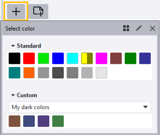


Other important printing settings
-
The advanced option XS_DRAWINGS_USE_CAP_HEIGHT_FOR_FONT_HEIGHT controls which font height system is used in printing, CAP font height or em font height (default). With CAP height, the font height is the same as the height of the capital letters of a specific font, andthe font height stays the same in export and printing. With em height, the font height is converted from one unit to another (em to CAP) in export and printing, and the result is many times an incorrect font height.
-
The advanced option XS_DRAWINGS_LINE_CAP_STYLE defines the line cap style in printing. You can have lines break in corners (value 0, default), round line corners (value 1), or rectangular line corners (value 2).
Print to multiple sheets
In the examples below, the numbers indicate the printing order of the sheets.
In this example, the option Bottom to top, right to left has been selected.

In this example, the option Left to right, top to bottom has been selected.

Print to multiple printers
You can print to more than one printer in one go based on the paper size of each selected drawing. When printing to multiple printers you typically have different printers for handling different paper sizes. Tekla Structures automatically selects the appropriate printer for each drawing.
To print to multiple sheets, you need to:
- Create and save the printing settings for the necessary printers. The printing settings also contain the color settings.
- Print by using Use multiple printers mode.
Create single printing settings
To be able to print to multiple printers, you first need to create single printing settings for each of the printers you want to print to:
-
On the File menu, click .
-
Select Use one printer.
-
Define the printing settings as desired on the Options tab and on the Line properties tab. Select the output type and printer, and define the paper size that this particular printer will handle in Use multiple printers mode.
-
Save the settings with a desired name by clicking Save.
-
Repeat this for each of the desired paper sizes. Do not use the size option Auto.
For example, you could create the following single printer settings files with the output type set to PDF file:
- PDF A4: Paper size set to A4, file prefix set to A4_
- PDF A3: Paper size set to A3, file prefix set to A3_
- PDF A2: Paper size set to A2, file prefix set to A2_
When printing a set of drawings in the multiple printers mode using the above single printer settings files, all A4 drawings will generate .pdf files with prefix A4_, all A3 drawings will have prefix A3_, and all A2 drawing will generate .pdf files with prefix A2_.
If you want to print more than one sheet size to the same printer in Use multiple printers mode, create a single printer settings file for each paper size, and specify the same printer in all of these files.

Print to multiple printers
-
In the Selected single printer settings files list, select the settings files to use in printing. You can select all or
just some of the single printer settings files.

The output type (printer, plot file, PDF file) is defined by each selected single printer settings file. Typically you would select settings files with the same output type. Output types lists the output types that are specified in the selected single printer settings files. The paper sizes defined in each printer settings file are shown next to Paper sizes.
