Shear tab plate connection (80)
Shear tab plate connection (80) connects a beam to a column, or a beam to a beam, with a shear tab that is bolted to the secondary part and welded to the main part. It is also possible to create flange stiffeners for beam to column connections and web stiffeners for beam to beam connections.
Objects created
-
Shear tab
-
Stiffeners
-
Bolts
-
Welds
Use for
| Situation | Description |
|---|---|
|
|
Beam connected to a column with a shear tab |
Selection order
-
Select the main part (column or beam).
-
Select the secondary part (beam).
The connection is created automatically when the secondary part is selected.
Part identification key

| Description | |
|---|---|
|
1 |
Shear tab |
Picture tab
Use the Picture tab to define the connection dimensions.
Dimensions

| Description | |
|---|---|
|
1 |
Horizontal distance from the main part to the first bolt |
|
2 |
Vertical distance from the secondary part upper edge and lower edge to the shear tab upper and lower edge |
|
3 |
Gap between the main part and secondary part By default, the gap value is zero. |
|
4 |
Distance from the secondary part upper and lower edge to the upper and lower flange of the stiffener By default, this distance is zero and the stiffener is created at secondary part upper and lower edge level. |
Parts tab
Use the Parts tab to define the part properties.
Parts
| Option | Description | Default |
|---|---|---|
|
Tab plate |
Thickness of the shear tab |
10 mm |
|
Upper fl. stiffener |
Thickness, width, and height of the stiffener |
|
|
Lower fl. stiffener |
Thickness, width, and height of the stiffener |
|
|
Web stiffener |
Thickness, width, and height of the stiffener |
|
Option |
Description |
Default |
|---|---|---|
|
Pos_No |
Prefix and start number for the part position number. Some components have a second row of fields where you can enter the assembly position number. |
The default part start number is defined in the Components settings in . |
|
Material |
Material grade. |
The default material is defined in the Part material box in the Components settings in . |
|
Name |
Name that is shown in drawings and reports. |
Parameters tab
Use the Parameters tab to define the beam cut, and the stiffener types and dimensions.
Beam cut and shear tab location
| Option | Description |
|---|---|
|
Beam cut |
|
|
Tab location |
Tab location in relation to the secondary beam web. Both creates two tab plates, one to the left and another to the right side of the web. The default is Left. |
Opposite web stiffener
| Option | Description |
|---|---|
|
Height |
|
|
Tolerance |
Vertical distance between the web stiffener and the main part flanges By default, the tolerance is zero. |
|
Angle |
Define the angle. By default, the angle is zero. |
|
Chamfer type |
Select the chamfer type. No chamfer usually causes a clash between the stiffener and the I profile rounding. |
|
Chamfer X |
Horizontal chamfer dimension For arc chamfers, the horizontal dimension is the radius of the arc. |
|
Chamfer Y |
Vertical chamfer dimension |
Flange stiffeners
|
Tolerance |
Distance between the flange stiffeners and the main part flanges By default, the tolerance is zero. |
|
Chamfer type |
Select the chamfer type. No chamfer usually causes a clash between the stiffener and the I profile rounding. By default, a line chamfer is created. |
|
Chamfer X |
Horizontal chamfer dimension For arc chamfers, the horizontal dimension is the radius of the arc. |
|
Chamfer Y |
Vertical chamfer dimension |
|
Direction |
|
General tab
Click the link below to find out more:
Design tab
Click the link below to find out more:
Analysis tab
Click the link below to find out more:
Bolt properties
Define the bolt properties and bolt group dimensions.
Click the link below to find out more:
|
Option |
Description |
Default |
|---|---|---|
|
Bolt size |
Bolt diameter. |
Available sizes are defined in the bolt assembly catalog. |
|
Bolt standard |
Bolt standard to be used inside the component. |
Available standards are defined in the bolt assembly catalog. |
|
Tolerance |
Gap between the bolt and the hole. |
|
|
Thread in mat |
Defines whether the thread may be within the bolted parts when bolts are used with a shaft. This has no effect when full-threaded bolts are used. |
Yes |
|
Site/Workshop |
Location where the bolts should be attached. |
Site |
Bolt assembly
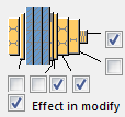
The selected check boxes define which component objects (bolt, washers, and nuts) are used in the bolt assembly.
If you want to create a hole only, clear all the check boxes.

To modify the bolt assembly in an existing component, select the Effect in modify check box and click Modify.
Welds
Click the link below to find out more:


