Create bolts
To create bolts, you can either create a single bolt group or apply a component that automatically creates bolt groups.
Tekla Structures uses the same command for creating bolts, studs and holes. If you want to create only holes, do not use any bolt elements (such as bolts, washers, and nuts).
If you want to create bolts without creating holes, use the No hole option for Special hole type in the Bolt properties.
You can create different marks for bolts and holes in drawings.
Create a bolt group
-
On the
Steel tab, hold down Shift and click Bolt
 .
.
The Bolt properties open in the property pane, and the following contextual toolbar appears:
-
Move the mouse pointer over the parts in the model to see a preview of the
bolts.
With the options
 and
and  where you use a part
face, the edge of the part face that is nearest to the mouse pointer is
selected as the basis for the preview. The bolt group direction will be
perpendicular to this edge.
where you use a part
face, the edge of the part face that is nearest to the mouse pointer is
selected as the basis for the preview. The bolt group direction will be
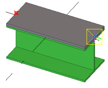
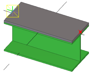
perpendicular to this edge.Bolt heads are shown with crosses in the preview. For example:
-
To adjust whether dimensions
are shown in the preview, click
 on the contextual
toolbar. Then click Internal dimensions to show or
hide the dimensions between the bolts in the group.
on the contextual
toolbar. Then click Internal dimensions to show or
hide the dimensions between the bolts in the group.
-
If you want to snap to part
center lines when you place the bolts, click
 on the contextual
toolbar. Then select whether you want to show the center lines for profiles,
such as beams and columns, or for plates, or for both.
on the contextual
toolbar. Then select whether you want to show the center lines for profiles,
such as beams and columns, or for plates, or for both.
-
Choose how you want to
create and place the bolts; click a button on the contextual toolbar to
select one of the three methods, By face, By parts and face, or
 By parts and points. Then follow the related steps below.
When you pick locations, you can use various snapping methods, such as numeric snapping, or you can create temporary reference points by holding down Ctrl.
If you need to change the direction of the bolts by 180°, click
 on the contextual
toolbar. Clicking only flips the bolt
direction, but maintains the other bolt properties, such as the order of
special holes and the hole locations.
on the contextual
toolbar. Clicking only flips the bolt
direction, but maintains the other bolt properties, such as the order of
special holes and the hole locations.To Do this Create bolts using a part face
-
On the contextual toolbar, click
. -
Pick a location on a part face.
To temporarily lock the edge direction, hold down Alt while you pick.
Tekla Structures uses the Cut length value in the Bolt properties to select the parts to be connected.
The part with the largest volume will be the main part, and the secondary parts will be in order that they are found.
Create bolts based on the parts to be connected and using a part face
-
On the contextual toolbar, click
. -
Select the main part, to which the secondary parts will be bolted.
-
Select the secondary parts.
-
Click the middle mouse button to finish selecting parts.
-
Pick a location on a part face.
To temporarily lock the edge direction, hold down Alt while you pick.
Tekla Structures calculates the bolt cut length based on the selected parts and corrects the Cut length value in the Bolt properties.
Create bolts based on the parts to be connected and by picking two points
-
On the contextual toolbar, click
. -
Select the main part, to which the secondary parts will be bolted.
-
Select the secondary parts.
-
Click the middle mouse button to finish selecting parts.
-
Pick a point to indicate the bolt group origin.
-
Pick a second point to indicate the direction of the bolt group x axis.
Tekla Structures determines the location of the bolt group using the following values: the bolt group x axis and the work plane. Dimensions are relative to the bolt group origin, which is the first point picked. Tekla Structures sets the x direction of the bolt group using the second point picked. It is important that the points you pick to create the bolt group are close enough to the parts you want to connect.
-
Create a single bolt
-
On the
Steel tab, hold down Shift and click Bolt to open the Bolt properties.
- Under Bolt group, select Array from the Shape list.
- In the Bolt dist X and Bolt dist Y boxes, enter 0.
- Create the bolt the same way you would create a bolt group. See the instructions in the table above.
Create bolts using the Auto bolt component
Use the Auto bolt component to bolt parts and nearby parts, shim plates, splice plates, or other plates. Auto bolt follows the part rotation and finds the best rotation so that you do not need to set the work plane. With Auto bolt one bolt group can span many parts, for example, manage a splice as a single group.
-
Click
the Applications & components button
 in the side pane to open the
Applications & components catalog.
in the side pane to open the
Applications & components catalog.
-
If needed, you can show cut length as temporary lines to view where the bolts should be placed even if they are not created.
-
Select
 in the list at the
bottom of the dialog to not show the temporary lines.
in the list at the
bottom of the dialog to not show the temporary lines. -
Select
 in the list at the
bottom of the dialog to show the temporary lines.
in the list at the
bottom of the dialog to show the temporary lines.
To delete the temporary lines, right-click the view and select Redraw view.
-
-
Pick the first and the second position to define the bolt group direction.
The positions you pick define a line that is used to find all parallel part faces and the optimal plane and locations for the bolts. The plane is chosen as follows:
-
The face with the longest projection of the line
-
If there are two faces with equally long projections, the face which is closer to the line
-
If there are two equally close faces, the larger face
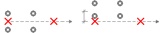
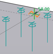
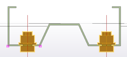
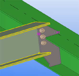
For example, with special part profiles, selecting points close to the wanted face ensures that the bolts are placed correctly:
-
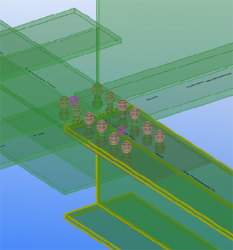
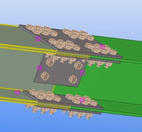
Examples
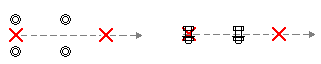
Examples of parts bolted using the Auto bolt component are shown below. The main parts and the selected points are highlighted.
Create a bolt group by exploding a component
An alternative way to create bolts is to first apply a component that includes bolt groups, and then explode the component.
Change or add bolted parts
You can change the parts a bolt group connects to.
- On the Steel tab, click Bolted parts.
- Select the bolt group.
- Reselect the main and secondary parts.
- Click the middle mouse button to finish selecting the parts.
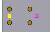
Bolt group shape
Use the Bolt group settings in the Bolt properties to select the shape of a bolt group and to determine how many bolts the bolt group contains.
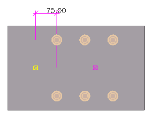
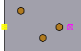
In the images below, the yellow handle indicates the origin of the bolt group, and the magenta handle indicates the x direction of the bolt group.
|
Shape |
Other bolt group settings |
Example values |
Result |
|---|---|---|---|
|
Array |
Bolt dist X Spacing between bolts, in the x direction of the bolt group. |
150 |
|
|
Bolt dist Y Spacing between bolts, in the y direction of the bolt group. |
100 |
||
|
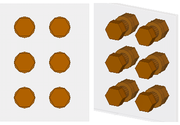
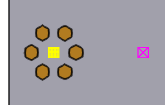
Circle |
Number of bolts |
6 |
|
|
Diameter of the bolt group |
100 |
||
|
List |
Bolt dist X x coordinate of each bolt, from the bolt group point of origin. |
75 175 250 |
|
|
Bolt dist Y y coordinate of each bolt, from the bolt group point of origin. |
75 -50 0 |
Bolt properties
Use the Bolt properties to view or modify the properties of a bolt group. Use the Holes section to define the properties of bolt holes. The units depend on the settings in .
|
Setting |
Description |
|---|---|
|
Bolt |
|
|
Size |
Bolt diameter. |
|
Standard |
Bolt assembly standard/grade. |
|
Bolt type |
Define whether the bolts are assembled on-site or in the shop. |
|
Connect as |
Indicate whether you are bolting a secondary part or a sub-assembly. |
|
Thread in material |
Indicate if the thread of the bolt can be inside the bolted parts. Tekla Structures does not use this value when calculating the length of full-threaded bolts. |
|
Cut length |
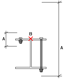
Indicate which parts the bolt connects. The value defines the area Tekla Structures should search for parts that belong to the bolt group. Using cut length you can determine whether the bolt will go through one flange or two. Tekla Structures searches for parts using half the cut length value, in both directions from the bolt group plane. In the illustration below, A is the cut length and B is the bolt origin. Tekla Structures calculates the search area as A/2 in both directions from point B.
Tekla Structures warns you if the cut length is too small (i.e. the bolt group contains no parts) and makes the bolt length 100 mm. If there are large gaps between the connected parts, the gap is added to the length of the bolt. Tekla Structures calculates bolt length using the total distance between the first and last surfaces. NOTE: If you want to force a bolt to be a certain length, enter a negative value for cut length (e.g. -150). NOTE: If holes or blind holes cannot be created, increase the cut length. |
|
Extra length |
Additional bolt length. Increases the material thickness that Tekla Structures uses when calculating bolt length. For example, you might need extra bolt length to allow for painting. You can also build additional lengths into bolt assemblies. |
|
Assembly |
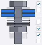
Select whether to create washers and nuts with the bolt. Select the Bolt checkbox to create the bolt, and then select the needed washer and nut checkboxes. For example:
If you want to create only holes without any bolts, clear all the checkboxes. |
|
Bolt group |
|
|
Shape |
Bolt group shape. You have the following options:
|
|
Bolt dist X |
Bolt spacing or coordinate, depending on the bolt group shape (Array or List). |
|
Bolt dist Y |
Bolt spacing or coordinate, depending on the bolt group shape (Array or List). |
|
Number of bolts |
Number of bolts in a circular bolt group. |
|
Diameter |
Diameter of a circular bolt group. |
|
Holes |
|
|
Tolerance |
Tolerance = Hole diameter - Bolt diameter |
| Plain hole type |
Select Through to create holes that are open throughout the part. Select Blind to create partial-depth holes that do not extend completely through parts. |
| Hole depth |
Depth of a blind hole measured from the bolt/hole reference points (yellow and magenta handles). Note that you may also need to adjust the Cut length value. |
|
Parts with special holes |
If you want to create oversized, slotted, or tapped holes, or if you want to omit holes, select the desired checkboxes to indicate which plies of the connection get special holes. |
|
Use the same settings for all special holes |
Select this checkbox to create similar special holes in each of the connected parts. The properties of the special hole that is closest to the bolt head will be used for all special holes in the bolt group. If you clear this checkbox, you can define special hole properties separately for each of the parts. |
|
Special hole type |
Oversized, slotted, tapped, or no holes. This option becomes active when you select one or more Special hole checkboxes next to Parts with special holes. |
|
Oversized |
Allowance of an oversized hole. |
|
Slotted hole X |
x allowance of a slotted hole. Zero for a round hole. To create slotted holes with an offset from the bolt center in the x direction, enter an offset value in the second box (Slot offset). |
|
Slotted hole Y |
y allowance of a slotted hole. Zero for a round hole. To create slotted holes with an offset from the bolt center in the y direction, enter an offset value in the second box (Slot offset). |
|
Core hole size |
Size of a predrilling hole. NOTE: The core hole size does not affect the DSTV output. This value is only for marking and representation of the hole in the model and drawings. |
|
The following two settings are available only in the Auto bolt component: |
|
|
Rotate slots |
If the bolt connects several parts, you may want to rotate alternate holes by 90 degrees. This allows the bolt to move in different directions. |
|
Show cut length as temporary lines |
Shows where the bolts should be placed even if they are not created.
|
|
Position |
|
|
On plane |
Move the bolt group perpendicular to the bolt group x axis.
|
|
Rotation |
Define how far the bolt group is rotated around the x axis, relative to the current work plane. For example, you can use this box to indicate on which side of the connected parts you want the bolt head to be.
|
|
At depth |
Move the bolt group perpendicular to the current work plane. |
|
Offset from |
|
|
Dx, Dy, Dz |
Offsets that move the bolt group by moving the bolt group x axis. Use to change the position of the bolt group. The start point values Dx, Dy and Dz move the first end of the bolt group, relative to the bolt group x axis. The end point values move the second end of the bolt group.
An example bolt group with the Dx start point set to 75:
|
|
More |
|
|
UDAs |
Click the User-defined attributes button to open the user-defined attributes (UDAs) of the bolt. UDAs provide more information about the bolts. |