Drawing improvements
Tekla Structures 2023 introduces a multitude of improvements to multiple drawing features and functions. From faster drawing opening to improved key plans and marks in multilingual projects, to being able to more easily relabel section and detail views, replace tables in drawings, and save layouts. Additionally, colors are now indicated with names in the drawing property pane, pull-out pictures have been simplified and improved, columns in the Drawing content manager have cumulative sorting, and dimensioning has been improved with more reliable dimension tags, improved filter dimensioning, and a new dimensioning type for neighbor parts.
Dimensioning improvements
Dimension objects on selected sides only
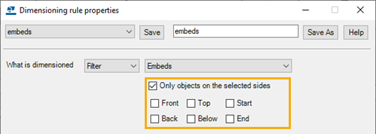
In the view-specific dimensioning, the dimensioning method Filter has a new Only objects on the selected sides check box in rule creation allowing you to only dimension objects that are on a certain side of the main part, for example, Front side. By creating separate rules for each side you can have front and back side objects dimensioned on separate dimension lines.
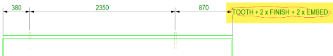
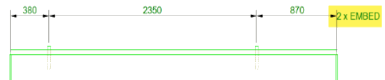
In the following example, front and back side objects are dimensioned on separate dimension lines:
Image

This improvement was already introduced in Tekla Structures 2022 SP2.
Better performance in Filter dimensioning method
Drawing dimensioning method Filter performance has been improved in large models.
Note:
This improvement changes the earlier guidance we gave when releasing Tekla Structures version 2021, that using a selection filter (.SObjGrp) would be faster than using a view filter (.vf). Now the view filter is faster, and we recommend using only view filters and no longer selection filters.
Filter method to dimension only objects visible in views
The Filter dimensioning method has been improved so that it does not dimension objects that are not visible in the drawing view. Previously, reinforcements were dimensioned although their visibility setting was Not visible.
Dimension tags in cast unit drawings updated correctly
Automatic dimensions and dimension tags are now updated correctly in cast unit drawings. Earlier, when you modified automatically added dimensions manually, or modified the model and reopened the drawing, extra dimension points or tags were sometimes added in the drawing, or dimension tags were updated otherwise incorrectly.
Before:
New dimensioning type for neighbor parts
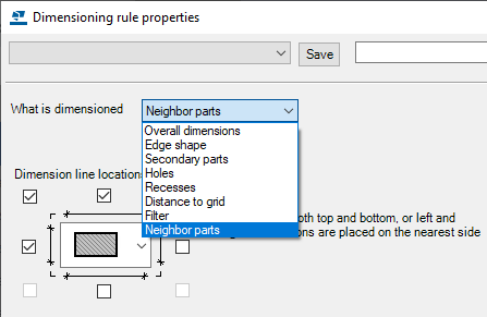
Now the neighbor parts have their own dimensioning type, Neighbor part dimensions. The new type is visible both in the drawing view properties and in the Dimensioning rule properties. The rule settings and the dimensioning functionality are the same as in the Secondary part dimensions. Note that this feature works best if the view size is extended so that neighbor parts are fully visible in the view.

Dimensions in rebar assembly drawings
The overall, filter, and grid dimensions are now working when the drawing only contains a rebar assembly.
Rebar group dimensioning
The performance of the Rebar group dimensioning tool has been improved.
Drawing mark content text loaded correctly in all languages
Previously, drawing mark setting files containing mark content text (<< Mark >>) did not load correctly when using a different user interface language. Now marks saved in one language can also be loaded in any other user interface language. This improvement applies to all part marks, view label marks, dimension marks and tags, and rebar dimension marks. Now the collaboration is easier in projects where team members use the Tekla Structures user interface in different languages.
An example of a mark content text location:

This improvement was already introduced in Tekla Structures 2022 SP2.
Key plans handled correctly in multilingual projects
Now key plans are handled and shown correctly in drawings also when the original model language and the current Tekla Structures language differ. This makes the collaboration easier in multilingual projects. The key plan information is now saved in the layout file (.lay). Earlier, the key plans were not found and an error message was displayed.
Improved pull-out pictures
Simplified rebar geometry in pull-out pictures
Rebar pull-out pictures now use the simplified Rebar Shape Recognition (RSR) geometry, which includes true arcs instead of segmented arcs. Where RSR recognizes a bent bar as straight, the straightened geometry is used.
Small arc segments in the pull-out pictures of rebars with curved legs are no longer showing any dimensions, bending radius, or bending angle graphics.
You can now create as simple as possible rebar pull-out pictures out of the most complex rebars so that the rebars can be visualized in an easily understandable way in drawings and reports.

Other rebar pull-out picture improvements
-
Rebar pull-out pictures of bars that have multiple arc legs, or arc and straight legs, now include a dimension showing the total length of the bar.
-
Previously, the bending angle tolerance for rebar pullouts was 0.2 degrees, which means that angles within 0.2 degrees of 90 or 0 were not displayed. The bending angle tolerance has now been increased to 0.5 degrees, to match the Rebar shape manager default value. This means that angles within 0.5 degrees of 90 or 0 are not displayed.
Colors indicated with names
The drawing property pane drop-down menus where you can select colors for various drawing objects now contain the names of the colors. This improves the software's accessibility by making it easier to identify the colors, for example.
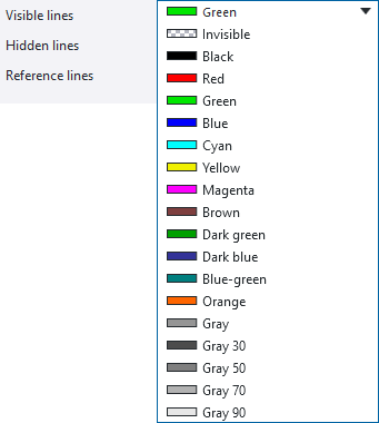
For more information about drawing colors, see Colors in drawings.
Improvements in Layout editor
For details about creating and editing editing tables in a drawing, see Create and edit drawing layouts.
New command to replace a table in a layout
With the new Layout editor context menu command Replace table you can replace tables in your layout. To replace a table, right-click the table in the layout and select Replace table.
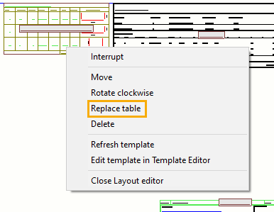
Replacing a table preserves all the settings that you have defined for the table that you replace. The new command eliminates the need to first remove a table in the layout, then add a new template, set the anchor point and alignment, and finally connect other tables around the new one.
Better usability in the Save layout dialog box
The user interface and the usability of the Save layout dialog box in Layout editor have been improved.
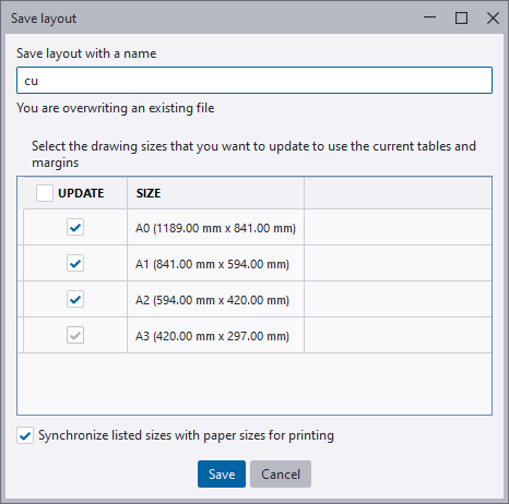
- The dialog box now has a minimum size, and it cannot be minimized so that the buttons are no longer visible.
- The dialog box now remembers its last location before closing.
- The Save layout with a name box is now wider than before.
- The Update and Size headers now use the same font.
New macro for relabeling section views


Relabel section views is a new drawing macro for updating section view labels. When section views have been removed from a drawing, this macro can be used for relabeling all the section views to have continuous numbering again.
This improvement was already introduced in Tekla Structures 2022 SP1.
New macro for relabeling detail views
Relabel detail views is a new drawing macro for updating detail view labels. When detail views have been removed from a drawing, this macro can be used for relabeling all the detail views to have continuous numbering again.

This improvement was already introduced in Tekla Structures 2022 SP1.
Drawing content manager - Cumulative column sorting
In Drawing content manager, the column sorting is now cumulative. Click a column to sort by that column first and then hold down Shift and click another column to secondarily sort by that column.

This improvement was already introduced in Tekla Structures 2022 SP4.
Drawing bolts perpendicular to parts
Earlier, the advanced option XS_DRAW_BOLTS_PERPENDICULAR_TO_PART_IN_SINGLE_DRAWINGS only worked in single-part drawings. Now it also affects how bolts are shown in single-part drawings included in multi-drawings, and in single-part views in assembly drawings.
This improvement was already introduced in Tekla Structures 2022 SP2.
Improvements in drawing opening performance
The most time consuming calculations have been identified and improved. Opening drawings containing the following types of objects is now considerably faster:
- Hatches in visible areas
- Large DWG reference files
- Large STP reference files
- Hole or recess symbols
- Complex concrete parts and profiles
- Cut rebar mesh
- Circular spiral rebars using the filled line representation
- Thousands of rebars
Rendering texts faster in FOG rendering
Text rendering is faster now in drawing FOG rendering.
To use FOG, set the advanced option XS_DRAWING_RENDERING_ENGINE to FOG. The default value is GDI.
Other drawing improvements
-
The Drawing tools macro has been removed from the Applications & components catalog.
-
The Create fillet, Create round chamfer, Create straight chamfer, and Copy with offset commands are all available on the drawing ribbon.
- The Create moment connection symbols macro is now available in the Applications & components catalog.
-
-
The mark leader line point tolerance circle has been reduced, making it possible to have smaller line segments in the leader line.