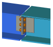
2L Splice (152)
2L Splice (152) connects a beam to a beam, or a column to a column with welded and bolted L profile angles.
Objects created
-
L profiles (angles)
-
Flange plates
-
Bolts
-
Welds
Use for
| Situation | Description |
|---|---|
|
|
Beam connected to a beam with welded and bolted L profile angles. |
Selection order
-
Select the main part.
-
Select the secondary part.
The connection is created automatically when the secondary part is selected.
Part identification key
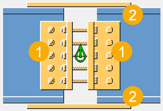
| Description | |
|---|---|
|
1 |
L profile angle |
|
2 |
Flange plate |
Picture tab
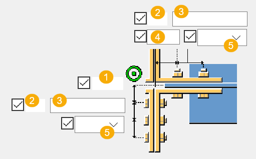
Use the Picture tab to define the connection dimensions, fitting types, and angle orientation.
Dimensions
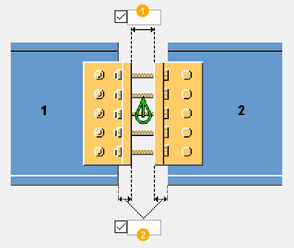
| Description | |
|---|---|
|
1 |
Distance between the L profile angles. |
|
2 |
L profile angle edge distance from the beam edge. |
Main part fitting type
| Option | Description |
|---|---|
|
|
Default Square fitting AutoDefaults can change this option. |
|
|
Automatic Square fitting |
|
|
Square Makes a vertical square cut to the end of the main part. |
|
|
Bevel Makes a vertical bevel cut to the end of the main part. |
|
|
Connection Cuts the end of the main part vertically parallel to the connection symbol. |


Secondary part fitting type
| Option | Description |
|---|---|
|
|
Default Square fitting AutoDefaults can change this option. |
|
|
Automatic Square fitting |
|
|
Square Makes a vertical square cut to the end of the main part. |
|
|
Bevel Makes a vertical bevel cut to the end of the main part. |
|
|
Cuts the end of the main part vertically parallel to the connection symbol. |


Angle orientation
| Option | Description |
|---|---|
|
|
Default Angles aligned with the secondary part. AutoDefaults can change this option. |
|
|
Angles aligned with the secondary part. |
|
|
Angles aligned with the main part. |
|
|
Angles aligned with the connection symbol. |


Parts tab
Use the Parts tab to define the part properties.
Parts
| Option | Description |
|---|---|
|
Secondary side L, Primary side L |
Select the profile from the profile catalog. |
|
Top Flg plate, Btm Flg plate |
Thickness and width of the top and bottom flange plate. Enter the thickness to create the plate. |
|
Option |
Description |
Default |
|---|---|---|
|
Pos_No |
Prefix and start number for the part position number. Some components have a second row of fields where you can enter the assembly position number. |
The default part start number is defined in the Components settings in . |
|
Material |
Material grade. |
The default material is defined in the Part material box in the Components settings in . |
|
Name |
Name that is shown in drawings and reports. |
|
|
Finish |
Describes how the part surface has been treated. |
Bolts tab
Use the Bolts tab to define the bolt group dimensions of the secondary part and the main part bolts, and the bolt properties.
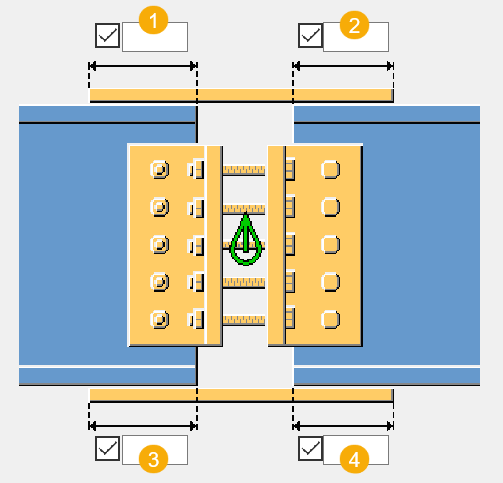
Bolt group dimensions
| Description | |
|---|---|
|
1 |
Dimension for vertical bolt group position. |
|
2 |
Number of bolts. |
|
3 |
Bolt spacing. Use a space to separate bolt spacing values. Enter a value for each space between bolts. For example, if there are 3 bolts, enter 2 values. |
|
4 |
Bolt edge distance. Edge distance is the distance from the center of a bolt to the edge of the part. |
| Description | |
|---|---|
|
1 |
Dimension for horizontal bolt group position. |
|
2 |
Number of bolts. |
|
3 |
Bolt spacing. Use a space to separate bolt spacing values. Enter a value for each space between bolts. For example, if there are 3 bolts, enter 2 values. |
|
4 |
Bolt edge distance. Edge distance is the distance from the center of a bolt to the edge of the part. |
|
5 |
Location where the bolts should be attached. |
Bolt basic properties
|
Option |
Description |
Default |
|---|---|---|
|
Bolt size |
Bolt diameter. |
Available sizes are defined in the bolt assembly catalog. |
|
Bolt standard |
Bolt standard to be used inside the component. |
Available standards are defined in the bolt assembly catalog. |
|
Tolerance |
Gap between the bolt and the hole. |
|
|
Thread in mat |
Defines whether the thread may be within the bolted parts when bolts are used with a shaft. This has no effect when full-threaded bolts are used. |
Yes |
Slotted holes
You can define slotted, oversized, or tapped holes.
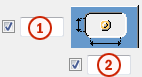
|
Option |
Description |
Default |
|---|---|---|
|
1 |
Vertical dimension of slotted hole. |
0, which results in a round hole. |
|
2 |
Horizontal dimension of slotted hole, or allowance for oversized holes. |
0, which results in a round hole. |
|
Hole type |
Slotted creates slotted holes. Oversized creates oversized holes. No hole does not create holes. Tapped creates tapped holes. |
|
|
Rotate Slots |
When the hole type is Slotted, this option rotates the slotted holes. |
|
|
Slots in |
Part(s) in which slotted holes are created. The options depend on the component in question. |
Bolt assembly
The selected check boxes define which component objects (bolt, washers, and nuts) are used in the bolt assembly.
If you want to create a hole only, clear all the check boxes.
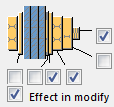
To modify the bolt assembly in an existing component, select the Effect in modify check box and click Modify.
Bolt length increase
Define how much the bolt length is increased. Use this option when, for example, painting requires the bolt length to be increased.

Parameters tab
Use the Parameters tab to define the flange plate overlap dimensions, angle orientation, and location.
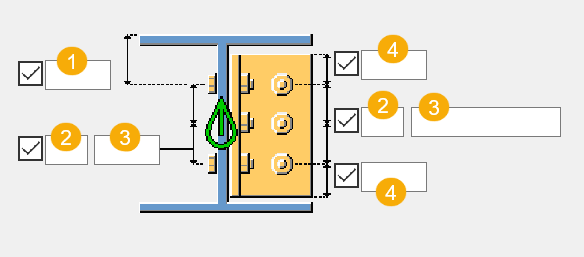
Flange plate overlap
| Description | |
|---|---|
|
1 |
Top plate overlap on the main part. |
|
2 |
Top plate overlap on the secondary part. |
|
3 |
Bottom plate overlap on the main part. |
|
4 |
Bottom plate overlap on the secondary part. |
Main part angle
| Option | Description |
|---|---|
|
|
Default Longest leg of the angle is perpendicular to the beam web. AutoDefaults can change this option. |
|
|
Longest leg of the angle is perpendicular to the beam web. |
|
|
Longest leg of the angle is parallel with the beam web. |


Secondary part angle
| Option | Description |
|---|---|
|
|
Default Longest leg of the angle is perpendicular to the beam web. AutoDefaults can change this option. |
|
|
Longest leg of the angle is perpendicular to the beam web. |
|
|
Longest leg of the angle is parallel with the beam web. |


Angle location
| Option | Description |
|---|---|
|
|
Default Angles are placed on the far and near side of the connection. AutoDefaults can change this option. |
|
|
Angles are placed on the far and near side of the connection. |
|
|
Angles are placed on the near side of the connection. |
|
|
Angles are placed on the far side of the connection. |


General tab
Click the link below to find out more:
Design tab
Click the link below to find out more:
Analysis tab
Click the link below to find out more:
Welds
Click the link below to find out more: