Reinforcement object properties in drawings
Use the options in reinforcement properties, rebar properties and rebar mesh properties to check and modify the rebar, rebar assembly, and rebar mesh visibility, appearance, and content. The neighbor reinforcement properties are the same as reinforcement properties.
To open reinforcement properties:
- On the Drawings & reports tab, click , select the drawing type, and navigate to reinforcement properties.
- In an open drawing, double-click the drawing view frame and select Reinforcement in the options tree.
- In an open drawing, double-click the drawing background, and navigate to reinforcement properties.
- Click reinforcement in an open drawing. If the property pane is not open, double-click the reinforcement.
- Select Rebar or Rebar mesh in the property pane object list.
- In an open drawing, go to Quick Launch, start typing reinforcement properties, and select Drawing reinforcement properties in the list. If you want to open mesh properties instead, start typing mesh properties, and select Drawing reinforcement mesh properties.
The following table lists all reinforcement properties on all property levels (drawing, view, object).
|
Option |
Description |
|---|---|
| Save, load and search properties in property pane | 
|
| Visibility of lines | Click the eye button to activate  or deactivate or deactivate  the options. the options. |
| Lines behind parts Hide lines behind parts (drawing and view level properties) |
Hide the lines behind the parts. This is useful, for example, with lifting anchors where the reinforcing bar is partly outside the part. If you wish to show embeds while hiding reinforcement, use the XS_HIDDEN_LINES_UNHIDE_EMBEDDED advanced option. |
| Lines behind other rebars Hide lines behind other rebars (drawing and view level properties) |
Hide the lines behind other reinforcement bar lines. |
| Rebar content, visibility and representation: | |
|
Visibility of all reinforcing bars |
This setting is only available on the drawing and view level. Visible shows the bars. Not visible does not show the bars. |
|
Representation type Representation (drawing and view level properties) |
single line draws a single line with radiused bends. single line with filled ends draws a single line for parallel bars and filled ends for perpendicular bars. double lines draws an outline of the bar with radiused bends. double lines with filled ends draws an outline of the bar with radiused bends and filled bar ends. filled line draws a solid bar with radiused bends. stick draws a single line without radiused bends. |
|
Visibility of reinforcing bars in group |
This setting is only available on the drawing and view
level. all shows all bars in a group or mesh. first bar shows only the first bar in the group or mesh. last bar shows only the last bar in the group or mesh. first and last shows the first and last bar in the group or mesh. bar in the middle of group shows one bar in the middle of the group or mesh. two bars in the middle of group shows two bars in the middle of the group or mesh. customized indicates that you have specified the location of the only visible reinforcing bar. Only applies to bar groups. |
| Straight end Symbol at straight end (drawing and view level properties) |
Select symbols to be used at straight ends.
Reinforcing bar end symbols are always drawn in a solid line type, regardless of the selected reinforcement line type. Only applies to reinforcing bars. |
| Hooked end Symbol at hooked end (drawing and view level properties) |
Select symbols to be used at hooked ends. Only applies to reinforcing bars. Reinforcing bar end symbols are always drawn in a solid line type, regardless of the selected reinforcement line type. |
| Mesh content, visibility and representation: | |
|
Visibility of all meshes |
This setting is only available on the drawing and view level. Visible shows the meshes in the drawing. Not visible does not show the meshes in the drawing. |
Representation type Representation (drawing and view level properties) |
single line draws a single line with radiused bends. single line with filled ends draws a single line for parallel bars and filled ends for perpendicular bars. double lines draws an outline of the bar with radiused bends. double lines with filled ends draws an outline of the bar with radiused bends and filled bar ends. filled line draws a solid bar with radiused bends. stick draws a single line without radiused bends. outline shows the shape of the mesh using an outline rectangle or polygon, and a diagonal line. Applies only to reinforcement meshes. outline (ignore holes) ignores holes and draws over them. Only applies to reinforcement meshes. |
|
Visible longitudinal bars Visibility of longitudinal wires (drawing and view level properties) Visible cross bars Visibility of crossing bars (drawing and view level properties) |
all shows all bars in a group or mesh. first bar shows only the first bar in the group or mesh. last bar shows only the last bar in the group or mesh. first and last shows the first and last bar in the group or mesh. bar in the middle of group shows one bar in the middle of the group or mesh. two bars in the middle of group shows two bars in the middle of the group or mesh. customized indicates that you have specified the location of the only visible reinforcing bar. Only applies to meshes. |
|
Mesh symbol |
Define the mesh symbol to be used. The mesh symbol appears in the middle of the diagonal line. Symbol 1 Symbol 2 Symbol 3 |
|
Mesh symbol size |
Define the size of the mesh symbol. |
| Rebar and mesh line properties: | |
|
Visible lines |
Define the color and type of the visible lines. You can use a standard color or a custom RGB color. Reinforcing bar end symbols are always drawn in a solid line type, regardless of the selected reinforcement line type. |
|
Hidden lines |
Define the color and type of the hidden lines. You can use a standard color or a custom RGB color. |
| Rebar assembly properties: | |
| Visibility of rebar assemblies |
This setting is only available in the view level properties. Visible shows the rebar assemblies. Not visible does not show the rebar assemblies. |
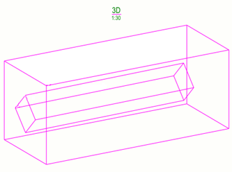
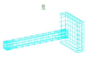
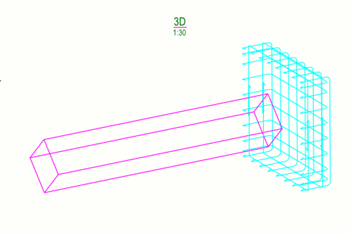
| Rebar Representation | This setting is only available on the view level. Outline: All sub-assemblies of the rebar assembly are shown as outline boxes.
As individual rebar objects: All rebar objects in the rebar assembly and sub-assemblies are visible.
|
|
Visible lines |
Define the color and type of the visible lines in rebar assemblies. You can use a standard color or a custom RGB color. Reinforcing bar end symbols are always drawn in a solid line type, regardless of the selected reinforcement line type. |
|
Mesh symbol |
This setting is only available on the view level. Define the mesh symbol to be used in rebar assemblies. The mesh symbol appears in the middle of the diagonal line. Symbol 1 Symbol 2 Symbol 3 |
|
Mesh symbol size |
This setting is only available on the view level. Defines the size of the mesh symbol in rebar assemblies. |
Additional ways of modifying reinforcement
In addition to the settings in reinforcement properties, you can modify the reinforcement in any of the following ways:
-
Increase the size of the bend and end symbols (in drawing units) using the advanced options XS_REBAR_BEND_MARK_SYMBOL_MIN_SIZE and XS_REBAR_END_SYMBOL_MIN_SIZE in .
-
Use the advanced option XS_REBAR_REVERSE_END_SYMBOLS in to change the end symbols to a different direction.
- Modify the reinforcing bar bending
schedule, rounding of bar dimensions, symbols for meshes, strands, and
unbonding, and appearance of reinforcement pull-outs in the
rebar_config.inpfile.
 . You can also
save the properties with another name.


