Create cutting planes
Cutting planes enable you to focus on a specific area of the model.
Everything on the positive side of the plane is hidden from the view, making it easier to work on remaining visible area.
Position a cutting plane
-
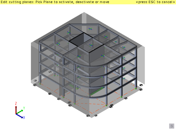
On the Edit tab, click
 Cutting Planes.
Tekla Structural Designer displays six cutting planes, initially forming a cube around the extents of the model.
Cutting Planes.
Tekla Structural Designer displays six cutting planes, initially forming a cube around the extents of the model.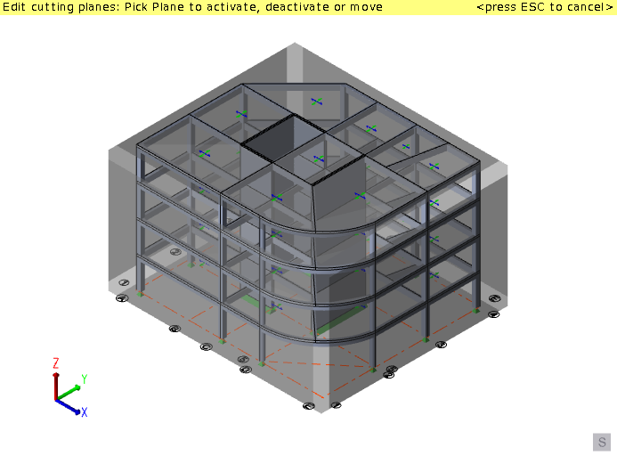
-
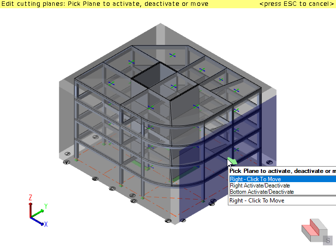
Click a cutting plane to activate it.
 When a cutting plane is active a
 symbol is displayed in
the corner of the view.
symbol is displayed in
the corner of the view.The active cutting plane faces are shown in a different color. (By default blue indicates the positive side of the plane and red the reverse side).
Anything on the positive side of the plane will be hidden from the view.
An arrow projects from the center of the cutting plane which can be used to reposition the plane.
-
Click the arrow at the center of the cutting plane.
 A dashed line indicates the direction in which you can move the plane.
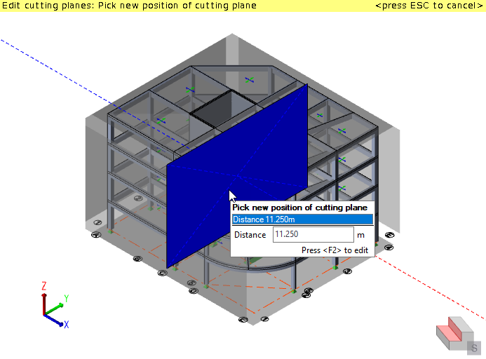
-
Click the desired position of the plane, or press F2 to type the exact distance.
Everything to the positive side of the plane is hidden.
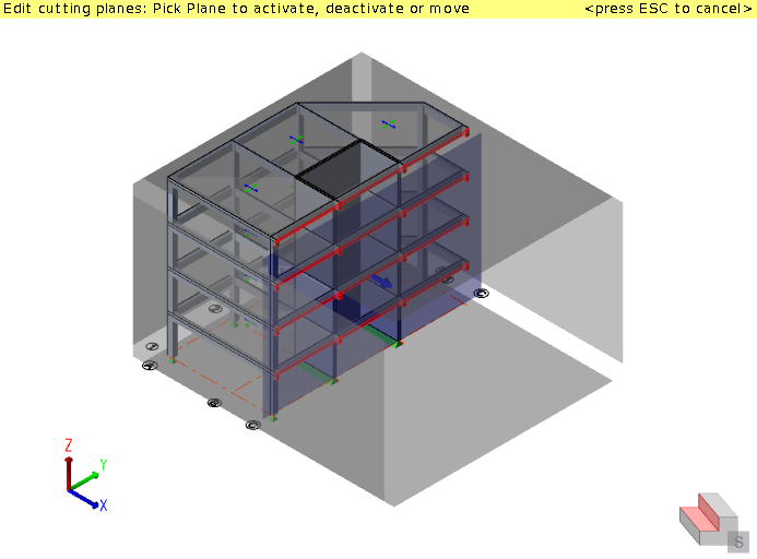
At this point you can activate and move further cutting planes if required, or press ESC to end the command.
-
Press ESC
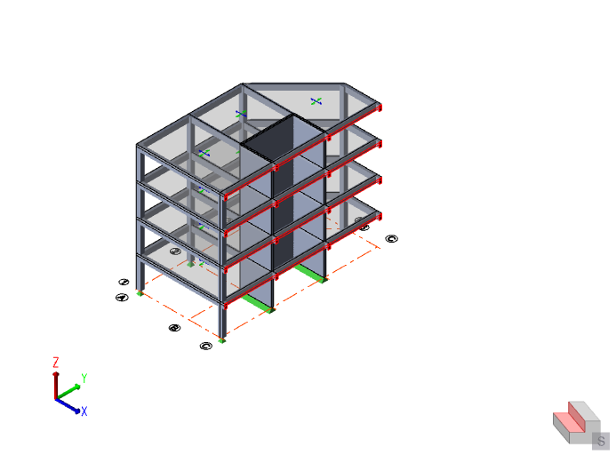 The six cutting planes are hidden, but the cutting planes icon remains in the bottom corner of the view to indicate that a plane is still activated.
Deactivate a cutting plane
The symbol in the corner of the
view indicates a cutting plane is active.
-
If cutting planes are not visible, click
Cutting Planes on the Edit tab to display them.
Tekla Structural Designer displays the cutting planes. Grey planes are deactivated, colored planes are activated.
-
Click an active cutting
plane to deactivate it.
Tip: If more than one cutting plane is listed in the tooltip, use the up or down cursor key to ensure the required one has been highlighted before picking it.
 The plane returns to its original gray color and
everything on its positive side is redisplayed.
The plane returns to its original gray color and
everything on its positive side is redisplayed.When all cutting planes have been deactivated the
symbol is removed. -
Press ESC to end the command.
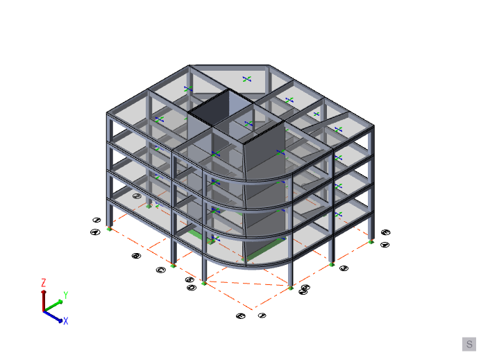 The cutting planes are hidden.
Activate and deactivate all cutting planes
Once
cutting planes have been positioned as required, you can quickly toggle the display
to switch between having them activated or deactivated. -
Click the Cutting Planes droplist on the ribbon and select Activate All
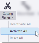 The cutting planes are activated.
 -
Press ESC to end the command.
-
Click the Cutting Planes droplist on the ribbon and select Deactivate All
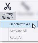 All six cutting planes are deactivated.
Align all cutting planes
Cutting planes can be aligned on plan to the global axes, the building directions, or a custom angle.
-
In the Properties window, set PlaneAlignment to 'Global axes'.

The cutting planes align to the global X and Y axes.
-
In the Properties window, set PlaneAlignment to 'Bld directions'.
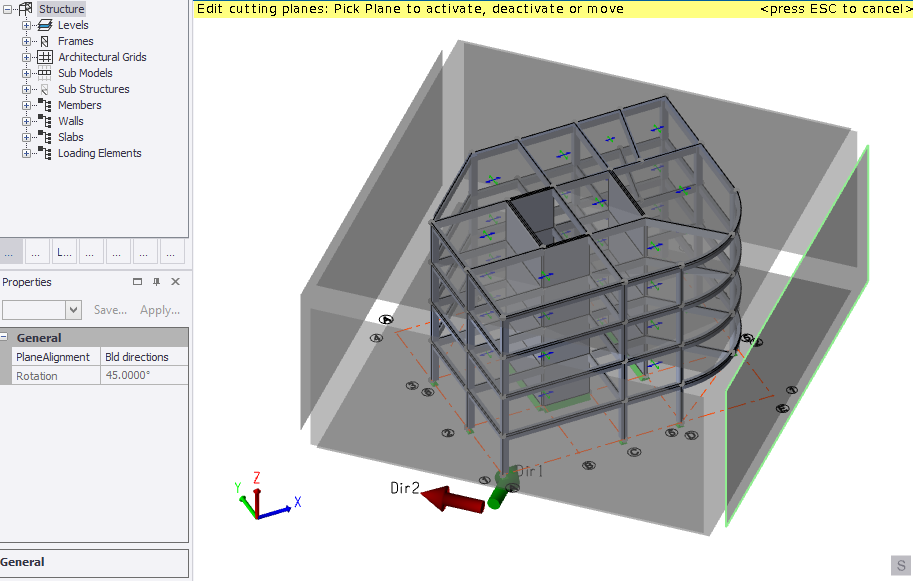
The cutting planes align to the Dir 1 and Dir 2 axes.
-
In the Properties window, set PlaneAlignment to 'Custom' and enter the Rotation
required.
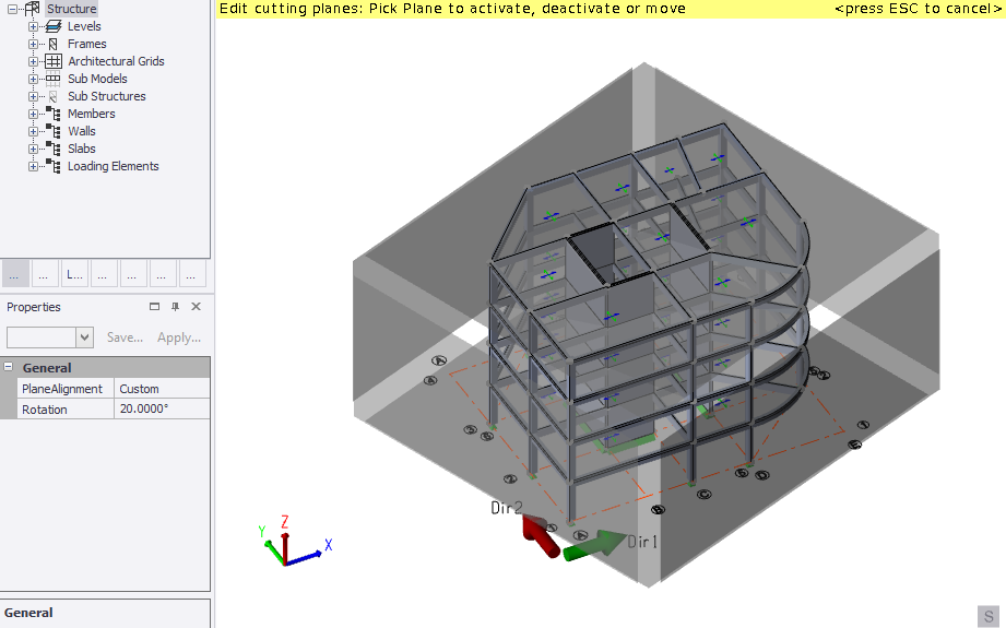
The cutting planes align to rotation angle specified.
Reset all cutting planes
-
Click the Cutting Planes droplist on the ribbon and select Reset All
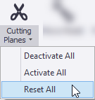 All the cutting planes are reset to their original positions.