Scene views and regimes
A scene view allows you to visualize and interact with a part of structure in a 3D or 2D window.
You control the functionality available in a scene view by assigning an appropriate view regime.
The amount of detail displayed in a scene view is controlled via the scene content window and once the detail level has been set as required you can choose to save it as a view configuration if required.
Various interface components are available within each scene view to assist in visualizing and manipulating the model.
If multiple scene views are open you can view them side by side by arranging them in tab groups.
Scene views
The following scene view categories are available:
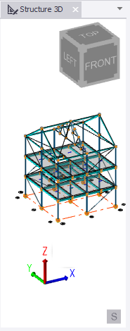
- Structure: A 3D view displaying the entire model.
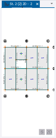
- Level: A 2D horizontal view of a specific level.
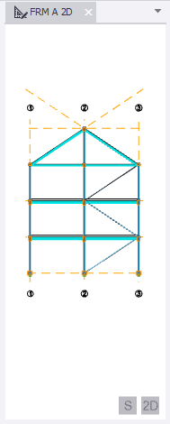
- Frame: A 2D vertical view of a specific frame.
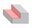
- Sloped Plane: A 2D inclined view of a sloped plane.
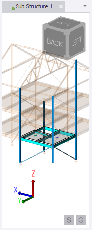
- Sub Structure: A 3D view of a sub structure
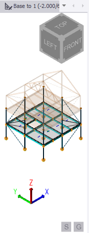
- Sub Model: A 3D view of a sub model.
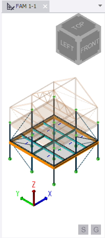
- FAM: A 3D view used of a footfall floor analysis model.
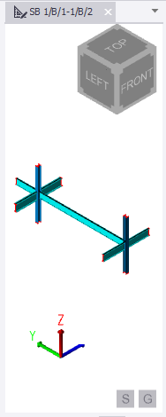
- Member: A 3D view of an individual member.
| Structure | Level | Frame | Sloped Plane |
|---|---|---|---|
|
|
|
|
| A 3D view of the entire model | A 2D horizontal view of a model level. | A 2D vertical view of a model frame, defined by grid lines. See: Create a frame |
A 2D view of a user-defined inclined plane. See: Create a slope |
| Sub Structure | Sub Model | FAM | Member |
|---|---|---|---|
|
|
 |
|
| A 3D view of a user-defined sub-set of the model which you can edit, design, or report in isolation. | A 3D view of a smaller analysis model generated during chasedown
analysis. See: Create sub models |
A 3D view of a floor analysis model generated during footfall assessment. | A 3D view of a Member. |
View regimes
A view regime determines the functionality of the active scene view.
There are 7 view regimes are as
follows:
| Icon | View regime | Used for |
|---|---|---|
 |
Structural View |
Creating the structure geometry and applying loads |
 |
Solver View |
Displaying the solver models for each of the analyses that have been performed. For more information, see: Solver models |
 |
Results View |
Viewing analysis results. For more information, see: Display analysis results in a Results View |
 |
Wind View |
Displaying the wind model, including wind zones and loads. For more information, see: Modify wind zones and wind zone loads |
 |
Review View |
Examining the design status or reviewing specific model properties. For more information, see: Review models |
 |
Slab Deflections View |
Displaying slab deflection analysis results. For more information, see: Slab deflections handbook |

|
Footfall Analysis View |
Creating and reviewing footfall floor analysis models. For more information, see: Footfall assessment handbook |
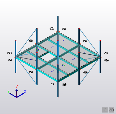
Scene view interface components
The main interface components are labeled in the 3D scene view (left) and 2D scene view (right) shown below:
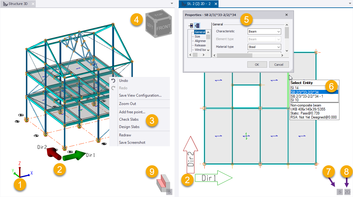
(1) The Global XYZ axis system within which all other systems exist.
(2) The Building Directions axis system indicates the principle axes of the building and can be rotated about global Z if required. These can be switched on/off (and their labeling can be controlled) via Structure Properties.
(3) Right-click anywhere within a 2D or 3D view to display a menu that is context-sensitive to the item that is currently highlighted.
(4) In 3D views, you can click a vertex, edge, or face of the ViewCube to rotate the model to a preset view. You can toggle the ViewCube on or off by pressing F8.
(5) The Properties dialog box can be opened by selecting Edit from the right-click context-sensitive menu. It is used as an alternative to the Properties window for viewing and editing parameters associated with an individual model object.
(6) The program is automatically in ‘select mode’ when no other commands are being performed. In this mode you can hover the cursor over an entity and its name will be displayed in the Select Entity tooltip. When the correct entity is displayed, click the entity to select it. If several entities are displayed, you select the one required by using the Tab key or Up/Down arrow keys.
(7) The Ghost Unselected  button is displayed in all 2D and 3D Views. It is used to
toggle the display of selected and unselected objects, making it easier to focus on
a particular subset of objects within the model. See: Use Ghost Unselected to focus on the selection.
button is displayed in all 2D and 3D Views. It is used to
toggle the display of selected and unselected objects, making it easier to focus on
a particular subset of objects within the model. See: Use Ghost Unselected to focus on the selection.
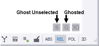
Similarly, the Ghosted  button is displayed in Sub Structure and Sub-model Views. It is
also displayed in Level, Frame, and Slope Views when they have been toggled into 3D
(via the 2D/3D toggle button). It is used to toggle the display of a ghosted view
allowing you to see the current view in the context of the whole structure. For more
information, see: Use Ghosted to see the view in the context of the whole model
and this video Ghosted Structure
view.
button is displayed in Sub Structure and Sub-model Views. It is
also displayed in Level, Frame, and Slope Views when they have been toggled into 3D
(via the 2D/3D toggle button). It is used to toggle the display of a ghosted view
allowing you to see the current view in the context of the whole structure. For more
information, see: Use Ghosted to see the view in the context of the whole model
and this video Ghosted Structure
view.
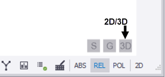
(8) The 2D/3D  button is
displayed in 2D Scene Views only. It is used to toggle the view between 2D and a 3D
isometric projection.
button is
displayed in 2D Scene Views only. It is used to toggle the view between 2D and a 3D
isometric projection.
button is
displayed in 2D Scene Views only. It is used to toggle the view between 2D and a 3D
isometric projection. Example of a level view in 2D:
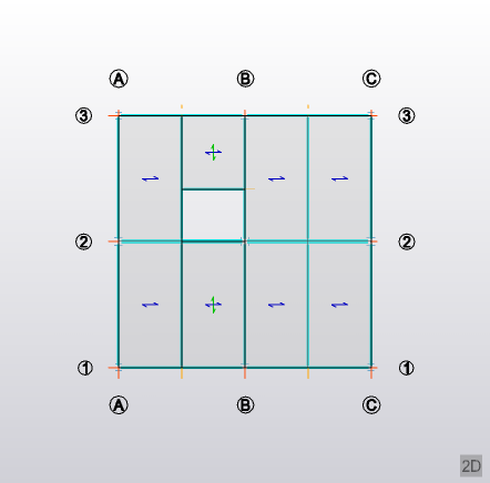
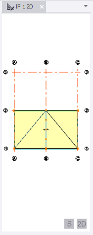
The same level view when toggled to 3D:
(9) The Cutting Planes symbol is displayed in the bottom right corner of the scene view when any of the cutting planes are currently active.
(10) The View regime buttons in the status bar can be used to switch the active view between different regimes to suit the task being performed.
(11) You select how much of this information is displayed in each scene view via Scene Content
Multiple scene views can be displayed simultaneously, either horizontally, or vertically, by dragging a view tab and docking it to create a new tab group.