Add variables to a custom component
Variables are the properties of a custom component. You can create variables in the custom component editor and use them to adapt custom components to changes in the model. Some of the variables appear in the custom component's dialog, while others are hidden and are only used in calculations.
Variable types
There are two types of variables:
-
Distance variable: The distance between two planes, or between a point and a plane. A distance variable binds parts together, or works as a reference distance.
-
Parametric variable: Controls all other properties in a custom component, such as name, material grade, and bolt size. Parametric variables are also used in calculations.
Distance variables
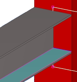
Use distance variables to bind custom component objects to a plane, so that the component objects stay at a fixed distance even if the surrounding objects change. You can create distance variables manually or automatically.
Use the handles of the following custom component objects to bind them to a plane:
-
parts (only custom component objects)
-
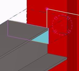
bolt groups
-
reinforcing bars
-
reinforcement meshes and strands
-
chamfers
-
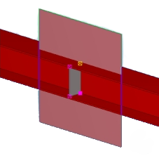
part cuts, polygon cuts, line cuts
-
fittings
-
construction planes
You can decide which distance variables are shown in the custom component's dialog. Show the variables if you want to edit their values in the dialog. Hide the variables if you only use them to bind objects to a plane.
Parametric variables
Use parametric variables to set properties for any object the custom component creates. After creating a variable, you can change its value directly in the custom component's dialog.
You can also create formulas to calculate values. For example, you can calculate the position of a stiffener relative to the beam length.
You can decide which parametric variables are shown in the custom component's dialog. Show the variables if you want to edit their values in the dialog. Hide the variables if you only use them in calculations.
Note:
There are some limitations concerning the variable names.
-
To be able to correctly reference a variable in your formula, the variable name must be 19 characters or shorter. Variables with longer names will not work correctly when referenced.
-
Variable names cannot contain mathematical operators (
+,-,*,/). -
You cannot use a mathematical constant, such as
PIore, as a variable name.
Plane types in distance variables
When you add distance variables to a custom component, or to a model, you must select a plane type. The plane type defines which planes you can select.
You can change the plane type when the Create distance command is active.
Boundary planes and component planes work for most profile types, so try to use them rather than outline planes whenever you can.
|
Plane type |
Description |
Example |
|---|---|---|
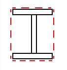
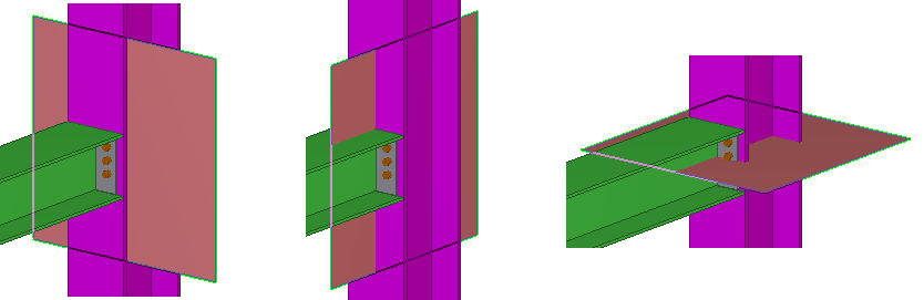
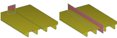
|
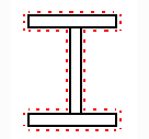
Boundary planes |
You can select the edges of a bounding box that surrounds the profile.
|
|
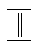
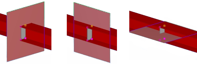
|
Center planes |
You can select the center planes of a profile.
|
|
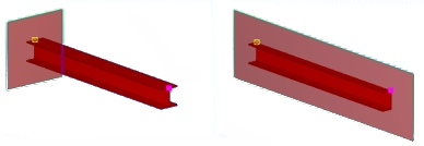
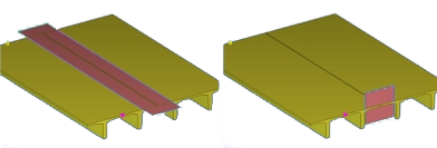
|
Outline planes |
You can select the outer and inner surfaces of a profile.
|
|
|
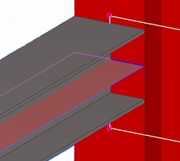
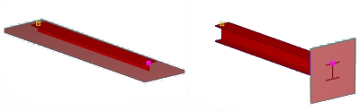
Cut planes |
If the part contains line, part, or polygon cuts, this option enables you to select cut surfaces. Fittings cannot be selected. |
|
|
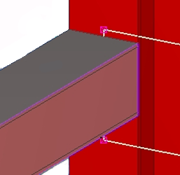
Component planes |
What you can select depends on the component type and the Position type of the custom component.
Connection component planes
Detail component planes
Part component planes
Seam component planes
|
|
Note that when you create distance variables in a model and bind model object handles to different planes, select the plane type from the third list on the Snapping toolbar. Most of the plane type options there are the same as above, but Grid planes is available instead of Component planes.