Model views in Tekla Structures
A model view is a representation of a model from a specific location. Each view is represented in its own window within Tekla Structures. Selecting a part in a model view highlights the part in all open views.
View plane
Each model view has a view plane on which the grids are visible. The view plane is an imaginary flat surface.
View depth is the thickness of the displayed slice of the model, and it is measured starting from the view plane in both positive and negative directions. Only objects positioned within the view depth are visible in the model.
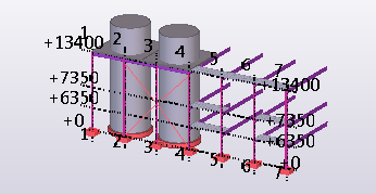
Points located on the view plane are represented as blue crosses. Points that are located outside the view plane are represented as red crosses.
You can move the view plane like any other object. When you move it, Tekla Structures only uses the vector that is perpendicular to the view plane. To move the view plane, click the model view, right-click and select .
Basic views
Basic views are those parallel to the global basic planes (xy, xz, and zy). In basic views, two axes always define the view plane and the axes appear in the plane name. The third axis is perpendicular to the view plane. It does not appear in the plane name. In the basic plane view, the model is shown from the direction of the third axis.
When you create basic views, you must define the view plane's distance (the view plane coordinate) from the global origin in the direction of the third axis. For more information, see Create model views.
Tekla Structures automatically assigns names for the basic views based on the plane and the coordinate.
Examples of basic views:
|
Plane |
3D view |
Plane view |
|---|---|---|
|
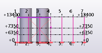
XY plan view, z-axis being the perpendicular axis |
|
|
|
XZ elevation view, y-axis being the perpendicular axis |
|
|
|
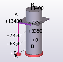
ZY elevation view, x-axis being the perpendicular axis |
|
|


Other views
For other view types, you either define the view plane and coordinate by picking points, or the points are defined automatically, depending on the creation method. For more information, see Create model views.
Position and arrange model views and drawings in the Tekla Structures window
Model views and drawings can be positioned and arranged around the Tekla Structures window using different docking zones.
To dock a model view or a drawing, drag the model view or drawing by its title bar towards to the Tekla Structures window edge in the direction where you want to dock it. As you drag and move closer to the window edge, blue highlighting shows where you can dock the model view or the drawing. There are nine predefined docking zones around the Tekla Structures window. Note that you can only dock the model views or drawings to the predefined docking zones; the model views or drawings do not dynamically identify empty areas. The docked positions for model views and drawings are saved and restored the next time you open the model.
Model views and drawings automatically resize and reposition themselves to fit the screen and avoid overlapping with each other or any open side pane windows. When you stretch one view, the others are automatically resized and adjusted. If you undock a model view or drawing, it reverts to its original size and position. The current active view is highlighted to ensure that you are working in the correct view.
Should I model in a 3D or plane view?
Model views can be 3D or plane views. 3D, plane, and also elevation views provide different types of information, which is useful for different tasks.
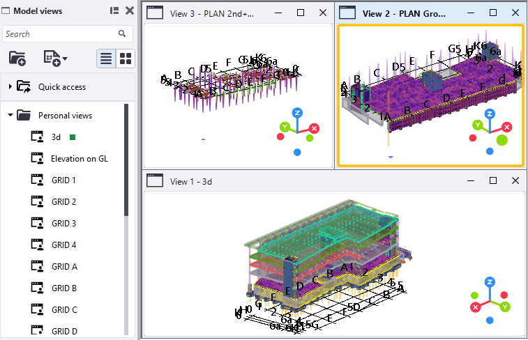
One common technique is to open several model views:
- A 3D view to see a real-life version of the model
- A plane view, where you can add and connect parts
- An elevation view to check the level
If you are working with several screens, maximize your work area by putting the different views on different screens.
You can easily switch between the 3D and plane view by using the keyboard shortcut Ctrl+P. For more information, see Switch between model views.