Cage ladder (S60)
Cage ladder (S60) creates a vertical step-through ladder with an option to create a safety cage.
Objects created
-
Rail bars
-
Rungs
-
Backer channel
-
Backer plates
-
Supports
-
Hoops
-
Vertical bars
-
Welds
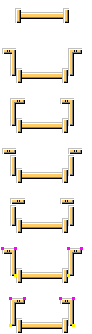
Selection order
-
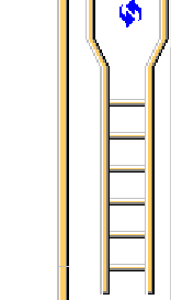
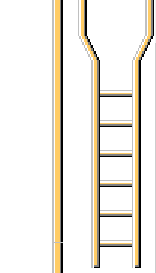
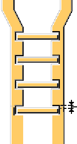
Pick a point to indicate the top point of the ladder.
-
Pick a point to indicate the elevation of the ladder.
The second point can be anywhere on the top of the bottom platform. The second point does not need to be directly below the first point but the two points should define a line that is nearly parallel to the current Z axis.
The ladder is created automatically when you pick the second point.
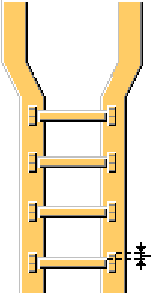
If the line between the two points is not nearly parallel to the Z axis, the ladder is not created. If the two points are suitable for creating the ladder, the second point is adjusted, if needed, to define a line that is perfectly parallel to the Z axis. The ladder is positioned relative to this reference line.
Before creating the component, we recommend that you set the user coordinate system so that the X axis and Y axis lie in a horizontal plane with the Z axis pointing straight up. The component works with other orientations as well, but regardless of the orientation, the ladder is always positioned exactly parallel to the Z axis.
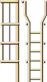
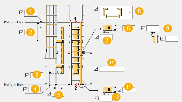
Part identification key
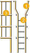
| Description | |
|---|---|
|
1 |
Rail bar |
|
2 |
Rung |
|
3 |
Cage |
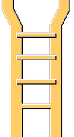
Picture tab
Use the Picture tab to define the ladder geometry and dimensions.
Dimensions
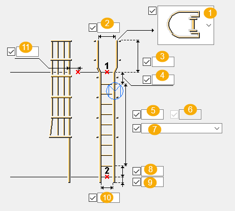
| Description | |
|---|---|
|
1 |
Step type Direction from which the ladder is accessed: left side, right side, or step through (default). |
|
2 |
Inside width of the ladder from the inner edge of one rail to the other The flared width is taken from the inner diameter of the hoops. Flared width is always set to more than the ladder width (10 ). If you set the flared width to less than or equal to the ladder width, the flared width is automatically reset to the ladder width plus 4 inches. If side steps are used, the ladder width is used as the width. |
|
3 |
Ladder top offset from the upper top of steel to the flared rail bar top edge |
|
4 |
Top rung offset Defines the distance from the first input point to the center line of the topmost ladder rung. |
|
5 |
Number of rungs To define the number of rungs, select either Default or Number of rungs from the list below the box (7). If side steps are used, four additional rungs are automatically added above the top platform at a spacing of 12 inches. |
|
6 |
Distance between the rungs |
|
7 |
Select to set either the maximum distance between the rungs, or the exact spacing from the bottom or top rung. |
|
8 |
Bottom rung offset Defines the distance from the second input point to the center line of the lowest ladder rung. |
|
9 |
Ladder bottom offset Defines the distance from the bottom platform to the bottom of the ladder rails. A positive value places the bottom of the ladder below the bottom platform. |
|
10 |
Ladder width Defines the inside width of the ladder from the inner edge of one rail to the other. If you select the step through option (1), the portion of the ladder above the top platform will be flared. If you do not define the ladder width, the default value in the applicable jobdefs.lis file is used. |
|
11 |
Toe offset Defines the distance from the center line of the ladder rail to the toe of the top platform. If you do not define this offset, the default value in the applicable jobdefs.lis file is used. |
Parts tab
Use the Parts tab to define the part profiles and properties.
Parts
| Option | Description |
|---|---|
|
Rail bars |
The bar profile used to form the ladder rails Select the profile from the profile catalog. |
|
Rungs |
The rod profile used to form the ladder rungs Select the profile from the profile catalog. |
|
Backer channel |
The channel profile used for the backer support channel Select the profile from the profile catalog. |
|
Backer plates |
The plate profile used for the bent plates that attach the ladder rails to the backer support channel Select the profile from the profile catalog. |
|
Ladder supports |
Select the profile from the profile catalog. |
|
Backside supports |
Select the profile from the profile catalog. |
|
Top hoops Bottom hoop Middle hoops |
The bar profile used to form the safety cage hoops Select the profile from the profile catalog. |
|
Vertical bars |
The bar profile used to form the vertical cage bars Select the profile from the profile catalog. |
|
Option |
Description |
Default |
|---|---|---|
|
Pos_No |
Prefix and start number for the part position number. Some components have a second row of fields where you can enter the assembly position number. |
The default part start number is defined in the Components settings in . |
|
Material |
Material grade. |
The default material is defined in the Part material box in the Components settings in . |
|
Name |
Name that is shown in drawings and reports. |
|
|
Class |
Part class number. |
|
|
Finish |
Describes how the part surface has been treated. |
Parameters tab
Use the Parameters tab to define the ladder properties and position.
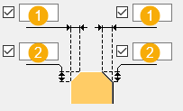
Horizontal position and offset
| Picture above | Description | Default |
|---|---|---|
|
Horizontal position |
Position of the ladder in the plane of the ladder
|
Middle |
|
Horizontal offset |
Lateral offset of the ladder in the plane of the ladder For example, an offset of 6" coupled with Horizontal position set to Middle places the center line of the ladder 6" to the right of the reference line. An offset of -8" with Horizontal position set to Right, for example, places the outside face of the right-hand rail 8" to the left of the reference line. |
0 |
Side rail cuts
|
Stringer cuts |
Select how the side rails are cut. |
|
Stringer max. length |
If you have selected to cut the side rails At max. length, define the maximun stringer length. |
Stringer rotation
Define how the stringers are rotated. The default value is top.

Ladder rotation
Define how the ladder is rotated. The default value is front.
Rung rotation
Define the rung rotation.
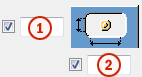
Cage creation
|
|
Default Cage is not created. AutoDefaults can change this option. |
|
|
Cage is not created. |
|
|
Cage is created. |
Rung stringer part cut
Select whether stringers are cut to avoid clashing.
| Option | Description |
|---|---|
|
|
Stringers are not cut. |
|
|
Stringers are not cut. |
|
|
Stringers are cut. Define the clearance value for the cut. |
|
|
Stringers are cut. Rungs are bolted to the stringers. Define the clearance value for the cut. |
|
|
Define the depth of the cut into the stringer. |

Chamfer dimensions
Define the chamfers at the top of the rail bars.
| Description | |
|---|---|
|
1 |
Horizontal dimension |
|
2 |
Vertical dimension |
Chamfer shape
| Option | Description |
|---|---|
|
|
No chamfer |
|
|
Line chamfer |
|
|
Convex chamfer |
|
|
Concave chamfer |


Cage tab
Use the Cage tab to define the size and position of the ladder's safety cage.
Cage dimensions
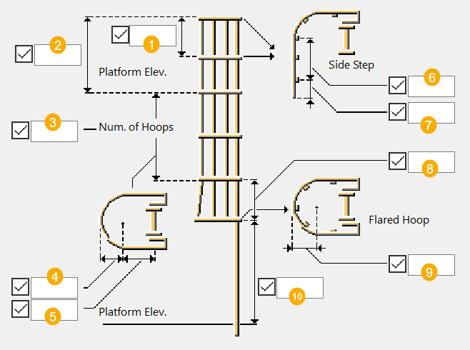
| Description | |
|---|---|
|
1 |
Distance from the center of the top flared hoop to the next higher hoop in the safety cage |
|
2 |
Distance from the top platform to the center of the top safety cage hoop |
|
3 |
Number of hoops (in addition to the required bottom flared hoop). The default number of hoops is 2. When you have selected that the ladder is accessed from the side, three additional hoops above the top platform are added at a spacing of 1'-10". When you have selected that the ladder has step-through access, two additional hoops are added at 12 inches and 3'-6" above the platform. |
|
4 |
Hoop radius Defines the outside radius of each safety cage hoop above the flared hoop at the bottom of the cage. The hoop radius at the bottom of the cage is determined by the flared radius. If you do not define the radius, the applicable jobdefs.lis file determines the default value. You can define a combination of dimensions, including the hoop radius and ladder width, that will make it impossible to bend and attach the hoops to the outside face of each rail. This applies especially to the top of a step-through ladder where the ladder rails are flared out for improved accessiblity. |
|
5 |
Cage depth Defines the distance from the center line of the ladder rails to the curvature point for all safety cage hoops. If you do not define the depth, the applicable jobdefs.lis file determines the default value. |
|
6 |
Side step dimension Defines the distance from the ladder's center line to the center line of the outermost vertical cage bar in the side step portion of the cage. When the step type is step through, this dimension is not used. |
|
7 |
Side step dimension Defines the distance from the center line of the outermost vertical cage bar to the end of the modified safety cage hoops. When the step type is step through, this dimension is not used. |
|
8 |
Flared hoop space Defines the distance from the center of the bottom flared hoop to the next higher hoop in the safety cage. |
|
9 |
Flared radius Defines the outside radius of the flared safety cage hoop at the bottom of the cage. The radius is equal to the hoop radius plus 1.75 inches. The radius of all other hoops is determined in the hoop radius (4). |
|
10 |
Flared hoop offset Defines the distance from the bottom platform to the center of the bottom flared safety cage hoop. If you do not define the offset, the applicable jobdefs.lis file determines the default value. |
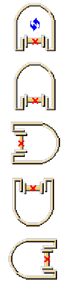
Hoop shape
| Option | Description |
|---|---|
|
|
U type hoop |
|
|
U type hoop |
|
|
O type hoop |
|
|
O type hoop Hoops are created at the inside face of the stringers. |


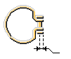
Vertical bar spacing
| Description | |
|---|---|
|
1 |
Define the angle between the vertical bars in the round section of the hoop. |
|
2 |
Define the distance between the vertical bars in the straight section of the hoop. |
Side step length projection of vertical bars
Define the length projection of the vertical bars when the cage is created with the left or right step type. You can select the step type on the Picture tab.
Bolts tab
Use the Bolts tab to define the bolt properties of the bolts used for backer, ladder, and backside support plates. If a backer channel is not created, the bolt settings are not used.
Bolt basic properties
|
Option |
Description |
Default |
|---|---|---|
|
Bolt size |
Bolt diameter. |
Available sizes are defined in the bolt assembly catalog. |
|
Bolt standard |
Bolt standard to be used inside the component. |
Available standards are defined in the bolt assembly catalog. |
|
Tolerance |
Gap between the bolt and the hole. |
|
|
Thread in mat |
Defines whether the thread may be within the bolted parts when bolts are used with a shaft. This has no effect when full-threaded bolts are used. |
Yes |
|
Site/Workshop |
Location where the bolts should be attached. |
Site |
Cut length
Defines the depth at which Tekla Structures searches for the sections of the bolted parts. You can determine whether the bolt will go through one flange or two.
Bolt assembly
The selected check boxes define which component objects (bolt, washers, and nuts) are used in the bolt assembly.
If you want to create a hole only, clear all the check boxes.
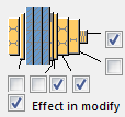
To modify the bolt assembly in an existing component, select the Effect in modify check box and click Modify.
Bolt length increase
Define how much the bolt length is increased. Use this option when, for example, painting requires the bolt length to be increased.

Slotted holes
You can define slotted, oversized, or tapped holes.
|
Option |
Description |
Default |
|---|---|---|
|
1 |
Vertical dimension of slotted hole. |
0, which results in a round hole. |
|
2 |
Horizontal dimension of slotted hole, or allowance for oversized holes. |
0, which results in a round hole. |
|
Hole type |
Slotted creates slotted holes. Oversized creates oversized holes. No hole does not create holes. Tapped creates tapped holes. |
|
|
Rotate Slots |
When the hole type is Slotted, this option rotates the slotted holes. |
|
|
Slots in |
Part(s) in which slotted holes are created. The options depend on the component in question. |
Anchor rods tab
Use the Anchor rods tab to define whether bolts or custom components are used as backer, ladder, and backside support anchors.
| Option | Description |
|---|---|
|
Bolt type |
Select whether bolts or custom components are used. |
|
Component |
Select the component from the Applications & components catalog. Define the custom settings, up direction, and rotation. |
Supports tab
Use the Supports tab to define the backer channel settings.
| Description | |
|---|---|
|
1 |
Top of the channel Top platform elevation distance from the top of the backer channel |
|
2 |
Top support offset Top platform elevation distance to the center line of the upper bent plate used to attach the ladder to the backer channel. If one backer channel support is created, the bottom support offset is used to control the position of the single bent plate. |
|
3 |
Bottom support offset Bottom platform elevation distance to the center line of the lowest bent plate used to attach the ladder to the backer support channel. If one backer channel support is created, this setting is used to control the position of the single bent plate. |
|
4 |
Bottom of channel Bottom platform elevation distance from the bottom of the backer channel. |
|
5 |
Backer offset Distance from the center line of the ladder rail to the nearest face of the backer channel. |
|
6 |
Vertical top backer support dimension |
|
7 |
Horizontal top backer support dimension |
|
8 |
Top backer support position |
|
9 |
Vertical and horizontal dimensions for top backer support created as polybeam |
|
10 |
Bottom offset to the middle backer support |
|
11 |
Vertical bottom backer support dimension |
|
12 |
Horizontal bottom backer support dimension |
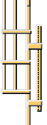
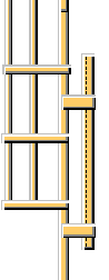
Backer channel
| Option | Description |
|---|---|
|
|
Default Backer channel is not created. AutoDefaults can change this option. |
|
|
Backer channel is not created. |
|
|
Backer channel is created to stiffen and support the ladder. |
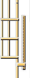
Backer channel supports
| Option | Description |
|---|---|
|
|
Default Two backer channel supports are created. The bent plate backer supports attach the ladder rails to the backer bar support channel. AutoDefaults can change this option. |
|
|
One backer support is created. |
|
|
Two backer supports are created. |
Top backer support position
Select how the top backer supports are positioned.
Bottom backer supports
| Option | Description |
|---|---|
|
|
Bottom backer supports are not created. |
|
|
Bottom backer supports are created at the outer edges. You can define the vertical and horizontal offset. |
|
|
Bottom backer supports are created at the inner edges. You can define the vertical and horizontal offset. |


Welds
Click the link below to find out more: