Stanchion curved (84)
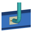
Stanchion curved (84) creates a connection plate and a bent stanchion part to connect a stringer and a stanchion.
Objects created
-
Connection plate
-
Bolts
-
Welds
Use for
| Situation | Description |
|---|---|
|
|
Connection plate and a bent stanchion part connect a stringer and a stanchion. |
Selection order
-
Select the main part.
-
Select the secondary part.
The connection is created automatically when the secondary part is selected.
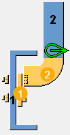
Part identification key
| Descripition | |
|---|---|
|
1 |
Connection plate |
|
2 |
Curved part |
Picture tab
Use the Picture tab to control the connection geometry.
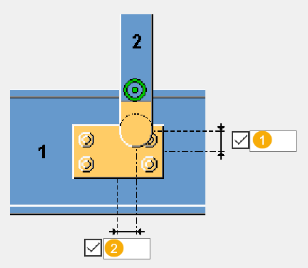
Dimensions
| Description | Default | |
|---|---|---|
|
1 |
Vertical distance between the connection plate center point and the center point of the connecting end of the stanchion. |
0 |
|
2 |
Connection plate eccentricity Horizontal distance between the connection plate center point and the stanchion center line. |
0 |
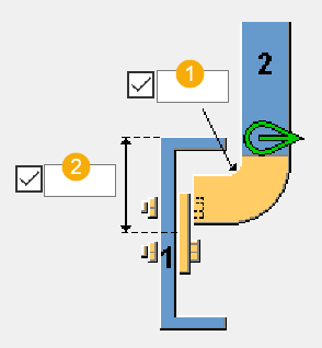
| Description | Default | |
|---|---|---|
|
1 |
Radius of the curved connection part |
90 degrees |
|
2 |
Connection plate vertical position Distance from the main part upper edge to the connection plate center line. |
76 mm |
Parts tab
Use the Parts tab to define the part properties.
Connection plate
| Option | Description | Default |
|---|---|---|
|
Connection plate |
Thickness and width of the connection plate. |
10 mm |
|
Option |
Description |
Default |
|---|---|---|
|
Pos_No |
Prefix and start number for the part position number. Some components have a second row of fields where you can enter the assembly position number. |
The default part start number is defined in the Components settings in . |
|
Material |
Material grade. |
The default material is defined in the Part material box in the Components settings in . |
|
Name |
Name that is shown in drawings and reports. |
Parameters tab
Use the Parameters tab to define the connection plate orientation and chamfers.
Method of construction
Select the method of construction and enter the fabricator name.
Plate type
| Option | Description |
|---|---|
|
|
Default Rectangular AutoDefaults can change this option. |
|
|
Rectangular |
|
|
Diamond |
|
|
Triangular |
|
|
Circular |
|
|
Rectangular by bolts The plate size is determined by the values you enter on the Bolts tab. |
|
|
Circular by bolts The plate size is determined by the values you enter on the Bolts tab. |
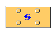
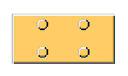
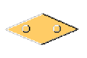
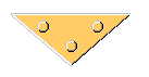
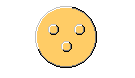
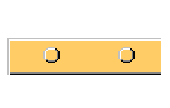
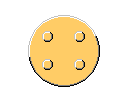
Plate orientation in skewed situations
| Option | Description |
|---|---|
|
|
Default Perpendicular to the secondary part AutoDefaults can change this option. |
|
|
Perpendicular to the secondary part |
|
|
Oriented to the main part |
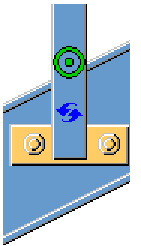
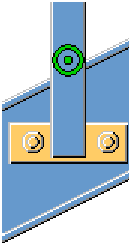
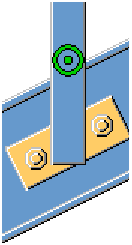
Plate orientation
| Option | Description |
|---|---|
|
|
Default Horizontal AutoDefaults can change this option. |
|
|
Perpendicular |
|
|
Horizontal |
Chamfer type
| Optio | Description |
|---|---|
|
|
Default No chamfer AutoDefaults can change this option. |
|
|
No chamfer |
|
|
Line chamfer Define the horizontal and vertical chamfer dimensions. |
|
|
Round chamfer Define the chamfer radius. |


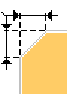

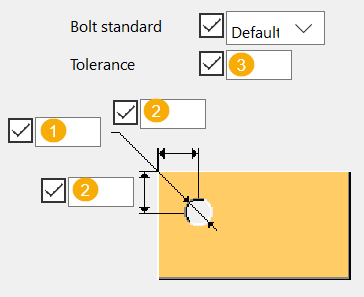
Bolt hole dimensions
| Description | |
|---|---|
|
1 |
Hole diameter |
|
2 |
Edge distance of the hole |
|
3 |
Select the bolt standard and define the hole tolerance. |
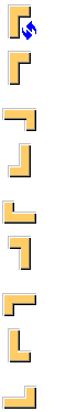
Cut orientation
Select the orientation of the cut.
Bolts tab
Use the Bolts tab to define the bolt properties.
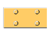
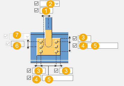
Bolt group dimensions
| Descpription | |
|---|---|
|
1 |
Dimension for horizontal bolt group position. |
|
2 |
Select how to measure the dimensions for horizontal bolt group position.
|
|
3 |
Bolt edge distance. Edge distance is the distance from the center of a bolt to the edge of the part. |
|
4 |
Number of bolts. |
|
5 |
Bolt spacing. Use a space to separate bolt spacing values. Enter a value for each space between bolts. For example, if there are 3 bolts, enter 2 values. |
|
6 |
Dimension for vertical bolt group position. |
|
7 |
Select how to measure the dimensions for vertical bolt group position.
|


Bolt basic properties
|
Option |
Description |
Default |
|---|---|---|
|
Bolt size |
Bolt diameter. |
Available sizes are defined in the bolt assembly catalog. |
|
Bolt standard |
Bolt standard to be used inside the component. |
Available standards are defined in the bolt assembly catalog. |
|
Tolerance |
Gap between the bolt and the hole. |
|
|
Thread in mat |
Defines whether the thread may be within the bolted parts when bolts are used with a shaft. This has no effect when full-threaded bolts are used. |
Yes |
Slotted holes
You can define slotted, oversized, or tapped holes.

|
Option |
Description |
Default |
|---|---|---|
|
1 |
Vertical dimension of slotted hole. |
0, which results in a round hole. |
|
2 |
Horizontal dimension of slotted hole, or allowance for oversized holes. |
0, which results in a round hole. |
|
Hole type |
Slotted creates slotted holes. Oversized creates oversized holes. No hole does not create holes. Tapped creates tapped holes. |
|
|
Rotate Slots |
When the hole type is Slotted, this option rotates the slotted holes. |
|
|
Slots in |
Part(s) in which slotted holes are created. The options depend on the component in question. |
Bolt assembly
The selected check boxes define which component objects (bolt, washers, and nuts) are used in the bolt assembly.
If you want to create a hole only, clear all the check boxes.

To modify the bolt assembly in an existing component, select the Effect in modify checkbox and click Modify.
Bolt length increase
Define how much the bolt length is increased. Use this option when, for example, painting requires the bolt length to be increased.

Staggering of bolts
|
Option |
Description |
|---|---|
|
|
Default Not staggered AutoDefaults can change this option. |
|
|
Not staggered |
|
|
Staggered type 1 |
|
|
Staggered type 2 |
|
|
Staggered type 3 |
|
|
Staggered type 4 |
General tab
Click the link below to find out more:
Design tab
Click the link below to find out more:
Analysis tab
Click the link below to find out more:
Welds
Click the link below to find out more: