Create bearing walls
Bearing walls provide resistance to vertical compressive loads (but not lateral loads) and support certain other member types. Unreinforced masonry walls, for example, can be modeled as bearing walls.
You can model bearing walls over several story heights. In these cases, Tekla Structural Designer creates a single wall with a uniform thickness between the base and top level.
Tekla Structural Designer determines the location of the wall from the alignment specified in the bearing wall properties, and the selected insertion points.
Note: Bearing walls do not perform the same
function as wall panels. In other words, bearing walls do not allow you to apply
loads calculated by the Wind Wizard to your structure.
Therefore, in order to apply wind loads, you must create additional wall panels in the same locations as the bearing walls.
Material type
Three Material types are available for bearing walls:
-
Concrete
-
Timber
-
General
Concrete Bearing Walls
There are two Concrete types available:
-
Normal
-
Lightweight
The Grade lists all the available grades in the Materials database under the current regional code for the selected Concrete type.
Timber Bearing Walls
The Grade lists all the available grades in the Materials database under the current regional code for Timber.
General Bearing Walls
The Grade lists all the available General materials in the Materials database under the current head code.
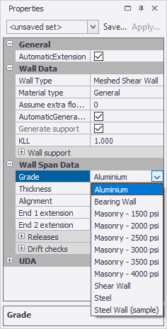
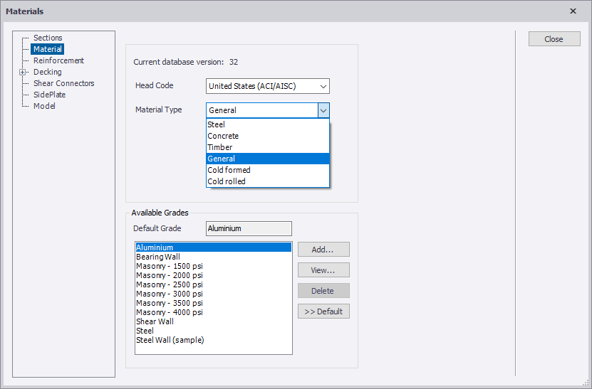
If the grade you want to use is not listed, you can open the Materials dialog and add the grade to the database, taking care to first select the General material type as shown below.
Geometric rules
- Bearing walls can only be created as rectangular in a vertical plane.
- Wall openings are ignored.
- Bearing walls cannot be included in cores.
Create bearing walls in a level view
Note: Ensure that you have defined the
construction levels between which the wall will run, and the grid points between
which the wall will lie.
-
On the
Model tab, click
 Bearing Wall.
The wall will adopt the properties displayed in the Properties window.
Create bearing walls in a frame or structure view
Note: In order to define a wall in a frame or
structure view, you must have already defined the construction levels between
which the wall will run and the grid points between which it will lie.
-
On the
Model tab, click
Bearing Wall.
The wall will adopt the properties displayed in the Properties window.
Bearing wall properties
Select one or more bearing wall and then use the Properties window to view and modify their properties.
| General | |
|---|---|
| Name | The automatically generated name. |
| User Name | Can be used to override the automatically generated name if required. |
| Top Level | Specifies the top level for the wall. |
| Base Level | Specifies the bottom level for the wall. |
| Wall Type | Bearing Wall Note: Bearing
walls must be rectangular in a vertical plane.
|
| Material Type |
Choice of:
|
| Assume extra floors supported | Enter the number of extra floors supported. |
| AutomaticGenerate Support |
• Cleared - a support will only be created if the Generate support property is checked. • Checked - a support will only be created if no members/slabs capable of providing support exist under the wall. |
| Generate support |
• Cleared - no support is created under the wall. • Checked - a support is created under the wall. Note: When a
support is created, a line support is formed under a
meshed wall, a point support under a mid-pier wall, and
a series of point supports under a bearing wall.
Note: When a
support is created, its degrees of freedom are as
specified in the ‘Wall support’ area of the wall
properties.
|
| Plane | Indicates the grid along which the wall is placed. |
| All panels | |
|---|---|
| Concrete type | While you can apply both normal and lightweight concrete, wall design using lightweight concrete is currently beyond scope. |
| Grade | The grades available here are set from the Materials button
on the Home ribbon. Note: The grade is only
required to specify the correct density to be used in the wall
self weight calculation. |
| Thickness | The thickness of the wall. Note: The thickness is
only required for the wall self weight calculation.
|
| Alignment |
Alignment of the wall:
|
| Alignment offset | When the alignment is set to User it can be adjusted by specifying an exact offset. |
| Live Load reduction [ACI/AISC], Imposed Load reduction [Other codes] | |
|
Override calculated value |
This option allows the user to specify their own percentage of load reduction to cater for situations where the automatically calculated value is inappropriate. |
| Wall support | |
|---|---|
| Angles (Fx/Fy/Fz, Mx/My/Mz) |
Used to specify the translational and rotational degrees of freedom in which the support acts: • Fixed - indicates the support is fixed in the specified direction. • Free - indicates the support is free to move, or has a stiffness applied in the specified direction. |
| Translational stiffnesses (x/y/z) |
Used to specify the translational stiffness applied in a direction that is not fixed: • Release • Spring Linear • Spring Non-linear |
| Rotational stiffnesses (x/y/z) |
Used to specify the rotational stiffness applied in a direction that is not fixed: • Release • Spring Linear • Spring Non-linear |
| Panel 1, 2, 3 etc. | |
|---|---|
|
In a multi-stack wall properties can be entered for a specific panel, over-riding those defined at the All panels level. |
|
| Count the floor as being supported | |
|---|---|
|
Top level (Interediate levels) Base level (Head Code Eurocode, BS or IS) |
If checked, the floor will be treated as supported when calculating the live/imposed load reductions. |
| Restrained | |
|---|---|
|
|
Used to indicate at which levels the wall is restrained. Note: Only
levels with a connecting member are listed.
|
| UDA | |
|---|---|
|
Name Finish Class Phase Note File |
A customizable list of the attributes that can be applied to individual members and panels. |