Create frames and slopes

Tekla Structural Designer
Modified: 14 Jul 2025
2025
Tekla Structural Designer

Create frames and slopes

A frame is a 2D view of the model, created in a vertical plane defined by an existing grid line. Since only the members that lie within the plane of the frame are displayed, a frame view can be particularly useful for defining bracing.

A slope is a 2D view of the model, created in an inclined plane. You can define a slope by selecting 3 existing grid points. Since only those members that lie within the plane of the slope are displayed, this type of view can be particularly useful for defining inclined roofs and ramps.

Create a frame
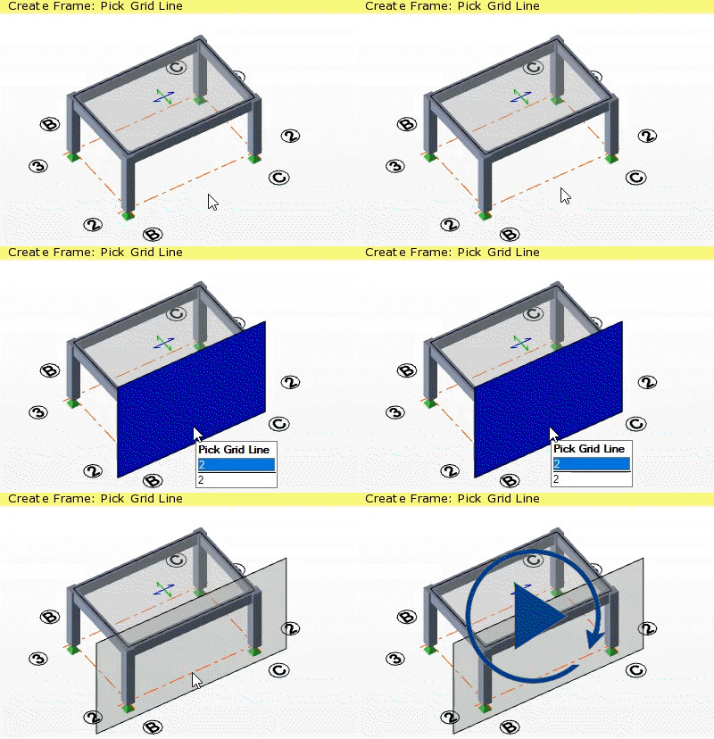
  1. Obtain a 3D view of your model where you can see the base grid line associated with the frame that you want to create.
  2. On the Model tab, click Frame.
  3. Position the mouse pointer over the grid line for the frame that you want to create.
  4. Click to create the frame.

    A frame for the selected grid line is added to the Frames branch of the Structure tree and a rectangle is displayed in the 3D view to illustrate the frame extents.

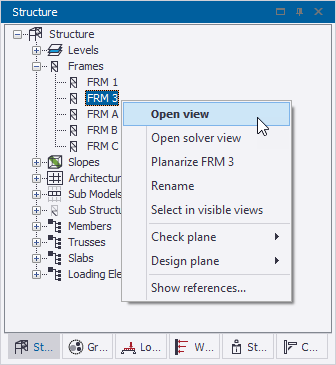
Open a 2D frame view

  1. In the Structure window, click the + sign on the left side of Frames
  2. Double-click on the name of the frame view, (or, right click and from the context menu select Open view).
    The frame view opens.
    Tip: If the Open view option is not available on the context menu, check if Visible has been unselected in the Frame properties.

Frame properties

Select a frame and then use the Properties window to view and modify its properties.

Property Description
Name Automatically generated, but can be replaced by User name if required.
Show grids in plane view

Controls whether the Grid & Construction Lines checkbox in Scene Content has any effect in plane views:

  • On = The Scene Content Grid & Construction Lines checkbox switches grid & construction lines on and off
  • Off = Grid & construction lines are always off, irrespective of the Scene Content Grid & Construction Lines checkbox setting
Show grids in 3D view

Controls whether the Grid & Construction Lines checkbox in Scene Content has any effect in 3D views:

  • On = The Scene Content Grid & Construction Lines checkbox switches grid & construction lines on and off for the specified frame
  • Off = Grid & construction lines are always off for the specified frame irrespective of the Scene Content Grid & Construction Lines checkbox setting
Note: This setting does not control the display of Architectural Grids which have a separate checkbox in Scene Content.
Visible

Controls whether the frame view can be opened or not.

Create a slope

Note:

Before creating a slope, note that:

  • In order to create a slope, you need to be able to click three existing (not co-linear) grid points that lie in the plane of the slope.

  • Grid points are formed at grid line intersections on construction levels. Therefore, if the points required to define the slope do not currently exist, you may need to insert new construction levels and grid lines to form them.

  • A sloped plane must be entirely contained within a single sub model because the sub model determines the mesh parameters to be applied.
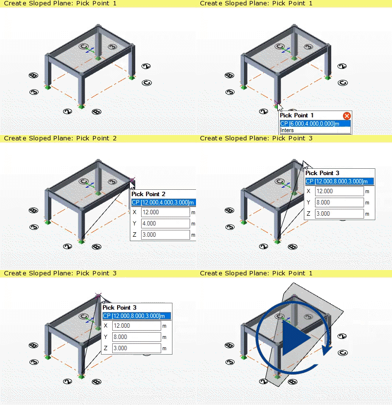
  1. Obtain a 3D view of your model where you can see three grip points that define the sloped plane.
    Tip:
    If you cannot see the grid line intersections on a particular construction level in the 3D view:
    1. In the Structure tree, select the level.

    2. In the Properties window, select the Show grids in the 3D view option.

      If you wish, you can clear the Show grids in the 3D view option for other levels to simplify the display.

  2. On the Model tab, click Sloped Plane.
  3. Click the three points which define the sloped plane.

    A sloped plane is added to the Slopes branch of the Structure tree and a polygon is displayed in the 3D view to illustrate the slope.

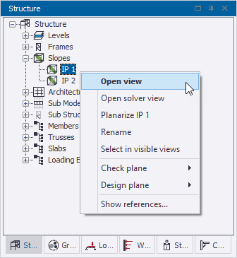
Open a 2D slope view

  1. In the Structure window, click the + sign on the left side of Slopes
  2. Double-click on the name of the slope view, (or, right click and from the context menu select Open view).
    The slope plane view opens.
    Tip: If the Open view option is not available on the context menu, check if Visible has been unselected in the Slope properties.
    Tip:

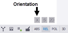
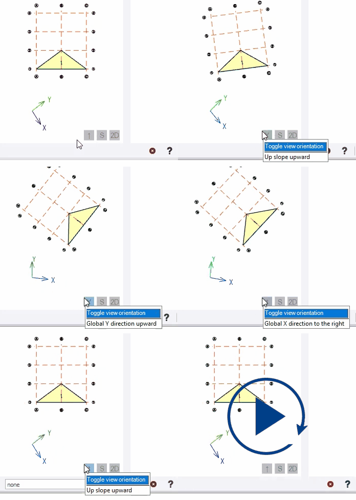
    The orientation of the sloped plane view is indicated on the orientation button located at the bottom right of the view.

    You can toggle between the options by clicking the orientation button.

    The button text changes to reflect the current orientation:

    - = Up slope upward

    - = Global Y direction upward

    - = Global X direction to the right

Slope properties

Select a slope and then use the Properties window to view and modify its properties.

Property Description
Type

The Sloped Plane type can be:

  • T.O.S = Top of Steel
  • S.S.L = Structural Slab Level
  • T.O.F = Top of Foundation
Note: Slabs are modeled above the level when it is set to T.O.S but below the level when it is set to S.S.L or T.O.F
Mesh slabs in 3D analysis
  • On = 2-way slabs (and 1-way slabs with the Analyze slab slab item property selected) are meshed in the 3D building analysis and grillage chasedown analysis in addition to the FE chasedown analysis.
  • Off = 2-way slabs (and 1-way slabs with the Analyze slab slab item property selected) are only meshed in the FE chasedown analysis.
Note: The Sub Model in which the Sloped Plane is contained determines the mesh parameters that are applied.
Name Automatically generated, but can be replaced by User name if required.
Show grids in plane view

Controls whether the Grid & Construction Lines checkbox in Scene Content has any effect in plane views:

  • On = The Scene Content Grid & Construction Lines checkbox switches grid & construction lines on and off
  • Off = Grid & construction lines are always off, irrespective of the Scene Content Grid & Construction Lines checkbox setting
Show grids in 3D view

Controls whether the Grid & Construction Lines checkbox in Scene Content has any effect in 3D views:

  • On = The Scene Content Grid & Construction Lines checkbox switches grid & construction lines on and off for the specified slope
  • Off = Grid & construction lines are always off for the specified slope irrespective of the Scene Content Grid & Construction Lines checkbox setting
Note: This setting does not control the display of Architectural Grids which have a separate checkbox in Scene Content.
Visible

Controls whether the slope view can be opened or not.

Show frame or slope references

The Show references command can be used to list all entities referenced by a selected frame or slope.

  1. Open the Frames or Slopes branch in the Structure tree.
  2. Right-click on the required frame or slope name.
  3. From the context menu, select Show References...

    All entities that are referenced by the selected frame or slope are listed in a dialog box. If entities are selected from the list they are highlighted in the 3D Structural view and their properties are displayed in the Properties window.

Was this helpful?
Previous
Next