接合梁和柱
您可以使用接合梁和柱节点,仅使用接合和切割来连接两根梁、两根柱或一根梁与一根柱。
用于连接零件的接合和切割可以通过多种方式放置。您可以定义在零件之间创建间隙,并使用焊缝来连接它们。
下表举例说明节点。
| 示例 | 描述 |
|---|---|
|
|
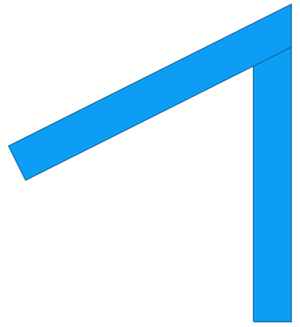
斜接节点 |
|
|
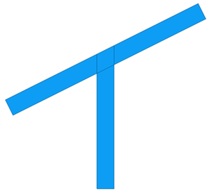
适合两个截面 |
|
|
两个截面之一未切割 |

-
从应用程序和组件目录中选择接合梁和柱组件。
-
要更改默认属性,请打开接合梁和柱组件对话框并在设置选项卡上修改属性。
-
定义主零件与次零件之间的间隙尺寸。如果您不输入任何值,则不会创建间隙。
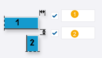
描述 1
主零件的切割平移
2
主零件与次零件之间的间隙
-
选择接合类型。
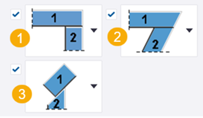
在列表 (1) 中选择的类型定义在列表 (2) 中可用的接合方法。对于接合类型选项,请参见下面的图片。
(3) 当主零件和次零件都倾斜时,选择是在腹板方向还是在翼缘方向创建接合。
接合类型选项如下:
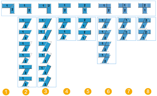
描述 1
斜接
2
次零件接合到主零件上,两个零件均接合。
3
主零件接合到次零件上,两个零件均接合。
4
次零件接合到主零件上,主零件不接合。
5
主零件接合到次零件上,次零件不接合。
6
次零件在主零件上交叠接合,两个零件均接合。
7
次零件在主零件上交叠接合,主零件不接合。
8
主零件在次零件上交叠接合,次零件不接合。
-
定义主零件与次零件之间的最大间隙尺寸。为此,请选择以下接合类型:
选择以下选项之一:
-
使用默认值
垂直接合次零件。

-
采用阈值的方法
定义间隙阈值距离。如果主零件和次零件之间的距离小于您定义的值,则垂直接合次零件。
在下面的示例图像中,距离为 150.0,而您定义的值为 200.0。
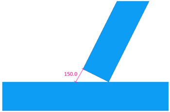
如果距离大于您定义的阈值,则次零件上的接合与主零件对齐。
在下面的示例图像中,定义的距离是 0。

-
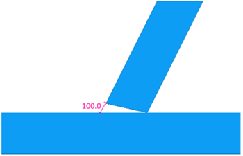
定义间隙
您定义的值用作接合次零件的距离。
在下面的示例图像中,定义的距离是 100.0。
-
-
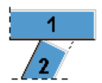
选择是接合主零件(1) 和次零件(2),还是使用线切割进行切割。
-
在零件组合中,选择零件的连接方式:
- 否:不连接零件。
- 浇筑体:次零件添加到主零件浇筑体中。
- 子构件:次零件添加到主零件浇筑体作为子构件。
- 用焊接:次零件焊接到主零件。
当您选择用焊接时,您可以在焊接选项卡上定义焊接属性。
-
在焊接选项卡上,定义焊接属性。
有关焊接属性的详细信息,请参见创建焊缝中的焊接属性一节。
-
单击 确认。
-
在模型中,选择主零件(梁或柱)。
-
选择次零件(梁或柱)。
选择次零件后会自动创建节点。