Bind component objects to a plane (create distance variables)
Use distance variables to bind component objects to a plane. Binding keeps the custom component at a fixed distance from the plane even if the surrounding objects change. Distance variables automatically get the prefix D (distance), which is shown in the Variables dialog.
You can create distance variables manually or automatically.
- Manual bindings require you to select the component object handles that you want to bind and select the plane you want to bind the handles to.
-
With automatic bindings Tekla Structures automatically creates dependencies between the selected component objects and existing planes, if the objects or their handles are located exactly on the plane.
Bind objects manually (create distances)
When you create distances by binding objects manually, you can bind a custom component object from specific handles only. You can bind an object to a maximum of three planes.
-
To make it easier to select
the handles, ensure that
Direct modification
 is switched
off.
is switched
off.
-
In a custom component view,
select an object that has handles, such as a part, bolt group, or part
cut.
Hold down the Alt key and use area selection (from left to right) to select multiple handles.
-
Select the handle that you want to bind to a plane.
-
In the custom component
editor, click the Create distance
 button.
You can also right-click and select Bind to plane.
-
Move the mouse pointer in a custom component view to highlight the plane
that you want to bind with the handles.
For example:
 Note:
Note:If you cannot highlight the correct plane, change the plane type on the Custom component editor toolbar. Boundary and component planes work for most profile types, so try to use them whenever you can.
-
Click the plane to create the binding.
Tekla Structures displays a distance symbol for the binding.
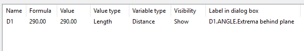
The corresponding distance variable is shown in the Variables dialog:
Note:
If you have created a nested custom component and have used a component of the type plug-in as a sub-component of a nested component, or another custom component as a sub-component of a nested component, the bindings may be lost or do not work as desired when you save the nested component and use it in a model.
Bind objects automatically (create automatic distances)
When you create distances by binding objects automatically, Tekla Structures automatically binds the custom component objects or their handles to existing planes if the objects or handles are located exactly on the plane. Tekla Structures creates bindings from up to three directions to the existing planes.
Tekla Structures selects planes in the following order:
- construction planes
- planes of the main and secondary parts
Note:
You cannot bind custom parts automatically, because they do not have a main part.
-
In the custom component editor, click the Automatically create distances for picked components' handle points
 button.
-
In a custom component view, select an object that has handles, such as a
part, bolt group, or part cut.
-
Click the middle mouse button to bind the object.
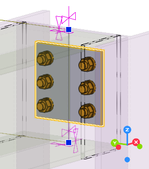
Tekla Structures binds the object from a maximum of three directions to the existing planes.
Tekla Structures displays a distance symbol for each binding. Select the object to see the bindings.
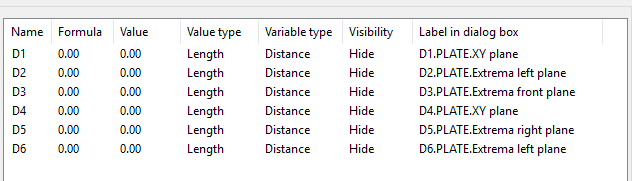
The corresponding distance variables are shown in the Variables dialog:
Test a binding
Test all bindings to see that they work correctly.
To be able to select distances in the model,
ensure that the Select distances
 selection switch
active.
selection switch
active.
-
Double-click the distance symbol in a custom component view.
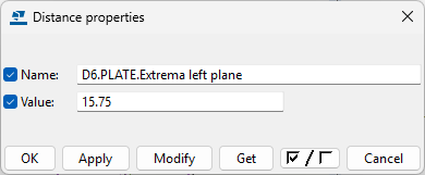
The Distance properties dialog opens.
Check a binding
You can check what is bound to what by using the Inquire object command.
To be able to select distances in the model, ensure that the Select
distances
selection switch
active.
-
On the ribbon, click
 Object.
-
Select a distance symbol in
a custom component view.
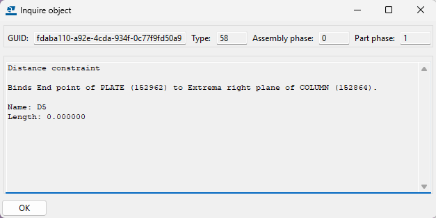
The Inquire object dialog shows information about the binding.
Delete a binding
Bindings cannot be modified, but you can delete the existing bindings and then create new ones to rebind the objects.
To be able to select distances in the model, ensure that the Select
distances
selection switch
active.
Example: Bind an end plate to a plane
This example shows how to bind the end plate top to the upper side of the beam.
-
To make it easier to select
the end plate handles, ensure that Direct modification is switched
off.
-
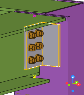
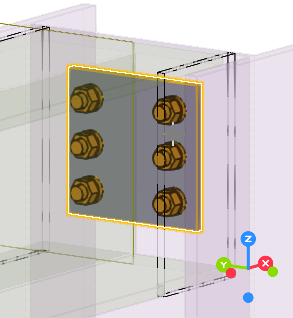
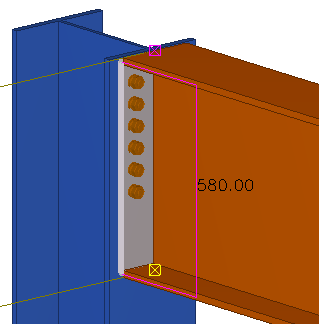
In a custom component view, select the end plate to see the end plate handles.
-
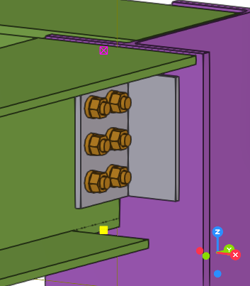
Move the pointer over the upper side of the beam flange to highlight it.
Here we are using the boundary plane type. If the part profile changes, the boundary plane is always found.
Note:If you cannot highlight the desired plane, change the plane type on the Custom component editor toolbar.
-
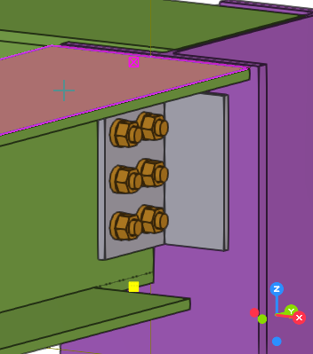
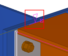
Click the upper side of the beam flange.
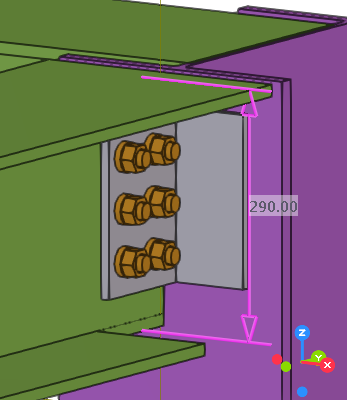
A distance symbol appears in the custom component views.
-
Give a descriptive name for the binding you created:
-
In the custom
component editor, click the Display variables
 button.
The Variables dialog opens.
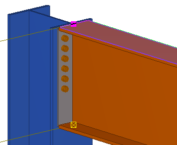
If you change the beam profile, the end plate top follows the upper side of the beam flange due to the binding.
-
In the custom
component editor, click the Display variables