Mark elements
Some elements can be added in all marks whereas some of the elements are specific to a mark type. The common elements and the mark-specific elements are listed below.
For information about mark properties, see Mark properties.
Common elements in marks
There are some mark element types that can be used in most of the mark types.
|
Element |
Description |
|---|---|
|
Text |
Add a text element in the mark and add your text there. |
|
Symbol |
Open a dialog where you can change the symbol file in use, and select a symbol to add to the mark. |
|
Template |
Add in the mark a custom graphical template created in Template Editor. Opens a dialog where you can select the template that defines the contents of the mark. For more information about adding templates in marks, see "Add templates in automatic marks". In mark templates, you can include detailed information of an embed or assembly, such as the sub-material used. Or you can use a template that changes the unit and the number of decimals in measurement values in a mark. You can also add graphical objects in templates using Template Editor tools. |
|
Add space < > |
Add spaces between mark elements. |
|
Remove space<-- |
Add a backspace between the desired elements to remove the default space between them. The default space between the elements depends on the text height and can be changed with the advanced option XS_MARK_ELEMENT_SPACE_FACTOR . |
| Frame | Add a frame around one or several elements, or around the whole mark depending on your selection. |
|
User-defined attributes Template attributes |
In the drawing and view level properties, you need to enter the attribute name in the displayed dialog exactly as it appears in the objects.inp file. In the property pane, add a user-defined attribute or template attribute in the mark by selecting it from the list of available attributes. To add a hidden attribute, type the name in the search box and press Enter. In marks, you
cannot use template attributes that refer to the whole model,
such as View labels do not accept any user-defined attributes, template attributes, or custom properties. For more information about adding user-defined attributes or template attributes in marks, see "Add attributes in automatic marks". |
| Custom properties |
Add a custom property in the mark from the list of available custom properties. |
Part mark elements
You can define part mark contents independently for main and secondary parts and for sub-assembly main and secondary parts.
The following table lists all elements specific to part marks and neighbor part marks.
For more information about part marks properties, see Mark properties.
|
Element |
Description |
|---|---|
|
Assembly position |
Adds the prefix and position number of the assembly. |
|
Part position |
Adds the prefix and position number of the part. |
|
Profile |
Adds the profile name of part, assembly, or cast unit main part. |
|
Material |
Adds the material of part, assembly, or cast unit main part. |
|
Name |
Adds the name of part, assembly, or cast unit main part. |
|
Class |
Adds the class of part, assembly, or cast unit main part. |
|
Finish |
Adds the finish of part, assembly, or cast unit main part. |
|
Size |
Adds the size of the part or the assembly or cast unit main part. |
|
Length |
Adds the length of the part or assembly, or of the cast unit main part. You can change the unit and format of the length. |
|
Camber |
Adds the camber of the part or the assembly or cast unit main part (if this user-defined part attribute is set). |
|
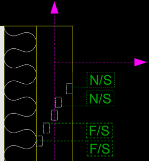
Fittings (NS/FS) |
Displays the near side/far side marks in the part mark. Only available in front views. The view plane defines whether the object is considered to be near or far side: If object is completely above the view plane, it is near side, if completely below, it is far side.
For more information about the view plane, see Work with model views. |
|
Face direction |
Displays main compass direction (North, East, South, West) of the face, where the mark is added. The direction can only be shown if
In other cases, the element produces no text to mark. Furthermore, face direction is not shown for columns in general arrangement drawings, if you have set Mark always to center of column in GA drawings to Yes in . |
|
Gage of outstanding leg |
Adds the hole gage. You can control the format of this option with the advance option
|
|
Center-to-center distance |
Adds center-to-center distance in the mark. You can control the format of this option with the advanced options XS_CENTER_TO_CENTER_DISTANCE_IN_ONE_PART_STRING and XS_CENTER_TO_CENTER_DISTANCE_IN_TWO_PARTS_STRING. |
|
Rotation angle |
Adds the rotation angle of a spiral beam in the mark. For other parts this element gives an empty value. |
Bolt mark elements
You can define bolt mark options independently for site and shop bolts.
Below is a list of the elements specific to bolt marks.
For additional information about defining size in bolt marks, see Define size in bolt marks using advanced options.
|
Element |
Description |
|---|---|
|
Bolt length |
Adds the length of the bolt. You can change the unit and format of the length. |
|
Bolt diameter |
Adds the bolt diameter. You can change the unit and format of the diameter. |
|
Hole diameter |
Adds the hole diameter. You can change the unit and format of the diameter. |
| Hole depth | Adds the hole depth |
|
Material |
Adds the bolt material grade. |
|
Standard |
Adds the bolt standard. |
|
Short name |
Adds the bolt’s short name. This can be the commercial name of a specific bolt, for example. |
|
Full name |
Adds the complete name of the bolt. This name is visible in the dialog list. |
|
Assembly type |
Adds the bolt assembly type. |
|
Number of bolts |
Adds the quantity of bolts. |
|
Slot length (x) Slot length (y) |
Adds the slot length in the x or y direction. You can change the unit and format of the length. |
|
Slot length |
Adds the slot length. You can change the unit and format of the length. |
|
Slot height |
Adds the slot height. You can change the unit and format of the height. |
|
Size |
Adds the hole size. You can also use certain advanced options to define the contents of the bolt mark Size element in different types of drawings. |
|
Countersunk |
Adds countersink in the countersunk bolt marks. |
|
Gage of outstanding leg |
Adds the hole gage. You can control the format of
this element with the advanced option XS_GAGE_OF_OUTSTANDING_LEG_STRING. The default value is
|
|
Center-to-center distance |
Adds the center-to-center distance between bolt holes. You can control the format of
this element with the advanced options XS_CENTER_TO_CENTER_DISTANCE_IN_ONE_PART_STRING (the default
value is |
Reinforcement and neighbor reinforcement mark elements
You can define mark contents separately for single reinforcing bars, bar groups, and reinforcement meshes.
Note:
To make the unit setting for the length attributes CC, CC_CROSS, CC_DIAMETER_CROSS, CC_DIAMETER_LONG, CC_EXACT, CC_EXACT_CROSS, CC_EXACT_LONG, and CC_LONG work in rebar marks and tags, you need to set the unit type to 'Length' in contentattributes_global.lst, which is the default value. If you leave the unit type empty, filtering using these attributes works but the unit settings do not. Here is an example line from contentattributes_global.lst of a situation where the unit settings work in drawings: CC_EXACT CHARACTER LEFT TRUE 20 0 Length mm.
Below is a list of the elements you can include in all reinforcement and neighbor reinforcements marks.
|
Element |
Description |
|---|---|
|
Name |
Adds the name of the bar or mesh. |
|
Grade |
Adds the material grade of the bar or mesh. |
|
Diameter |
Adds the nominal diameter of the bar. |
|
Class |
Adds the class of the bar or mesh. |
|
Length |
Adds the total length of the bar. You can change the unit and format of the length. |
|
Number |
Adds the quantity of the bars. |
|
Position |
Adds the reinforcement position number. |
|
Sequence position |
Adds the reinforcement sequence number. |
| Assembly position | Adds the position number of the associated rebar assembly. |
|
Shape |
Adds the shape of the bar or mesh. |
|
Weight |
Adds the weight of the bar or mesh. |
|
cc |
Adds the center-to-center spacing of the bars. The options are:
You can change the unit and format of the cc options. |
|
Pullout picture |
Adds a pull-out picture of a bar to the mark. For more information about pull-out pictures, see "Add pull-out pictures in automatic reinforcement marks". You can also add pull-out pictures in a reinforcement mark in an open drawing. |
| Layer |
Adds the layer of the reinforcement. |
Reinforcement and neighbor reinforcement mesh mark elements
You can define mark contents separately for reinforcement meshes.
The following elements are specific to the reinforcement and neighbor reinforcement mesh marks, other elements are the same as for reinforcement marks.
|
Element |
Description |
|---|---|
|
Size |
Adds the nominal diameters of the mesh bars, dimensions of the mesh, and the spacings of the bars in the longitudinal and crossing directions. |
|
Mesh length |
Adds the length of the reinforcement mesh. |
|
Mesh width |
Adds the width of the reinforcement mesh. |
|
cc |
You can define cc individually for the longitudinal and crossing bars in the mesh. Adds the center-to-center spacing of the bars. The options are:
|
|
Diameter longitudinal |
Adds the diameter or size of the longitudinal bars. |
|
Diameter cross |
Adds the diameter or size of the crossing bars. |
Elements in merged reinforcement marks
Some extra elements are available for merged reinforcement marks, in addition to basic reinforcement marks.
For more information about merging marks, see "Merge marks".
|
Element |
Description |
|---|---|
|
Block prefix |
Adds text or a value to the beginning of each repeated block. Opens a dialog where you can enter the prefix. You can use the following variables as block prefixes:
|
|
Single mark content |
Adds the content of the single reinforcement mark selected on the Content tab to the mark. |
|
Distances between groups |
Adds the center-to-center distances between reinforcing bars or bar groups included in a merged mark. Opens a dialog where you can enter the values. |
|
Symbol separating blocks in mark |
Adds a symbol between the blocks in the merged mark. Opens a dialog where you can define the symbol. The elements that appear before this element on the mark content list generate a block. |
Connection mark elements
In connection marks, you can show the connection code, name, number, and running number, the group they belong to, potential errors, and the related DSTV code.
|
Element |
Description |
|---|---|
|
Code |
Adds the connection code. This is a user-defined code you give for the connection in the connection dialog. The code can be either a text string or a number. |
|
Name |
Adds the connection name, for example, Tube_splice. |
|
DSTV code |
Adds the DSTV code. |
|
Connection number |
Adds the number of the connection. |
|
Running number |
Adds the connection running number. All connections are automatically numbered with a running number. |
|
Group |
Adds the connection group. |
|
Connection error |
Adds the connection error. The numbers correspond to the connection symbol colors:
|
Pour object mark elements
| Element | Description |
|---|---|
| Material | Adds the defined pour material. |
| Pour number | Adds the identifier that groups the pour objects in the same group, for example, to be poured at the same time. |
| Pour type | Adds a property of the pour based on the name of a part. |
| Concrete mixture | Adds the defined concrete mixture. |
Surface treatment mark elements
In surface treatment marks, you can show the name, material, Tekla Structures-specific name, and the code of the surface treatment.
|
Element |
Description |
|---|---|
|
Name |
Adds the name defined in the Name box in the surface treatment properties in a model. |
|
Material |
Adds the surface treatment material. |
|
Class |
Adds the class of the surface treatment. |
|
Code |
Adds the code of the surface treatment option selected from the Subtype list in the in the surface treatment properties in a model. For example, if the subtype is MF Magnesium Float, the code is MF. |
|
Surface treatment name |
Adds the full name of the surface treatment option selected from the Subtype list in the in the surface treatment properties in a model. For example, if the subtype is MF Magnesium Float, the full name is Magnesium Float. |
Section and detail mark elements
In section and detail marks, you can show the name of the section/detail, the name of the current drawing, and the name of the source drawing.
|
Element |
Description |
|---|---|
|
Section name/Detail name |
Adds the name of the section or the detail (A, B, C, and so on). |
| Drawing name |
Adds the name of the current drawing. |
|
Source drawing name |
Adds the name of the drawing where the view is. |
|
Source drawing name when moved |
Adds the name of the drawing where the view is. This is shown only if the view is not in the same drawing as the section/detail mark. |
View, section view and detail view label mark elements
In view labels, you can show the name of the view, section or detail, the view scale, drawing name, and source drawing name.
|
Element |
Description |
|---|---|
|
View name/Section name/Detail name |
Adds the name of the view, section or the detail. |
|
Scale |
Adds the scale of the view. |
|
Drawing name |
Adds the name of the current drawing. |
|
Source drawing name |
Adds the name of the drawing where the view has originally been created. |
|
Source drawing name when moved |
Adds the name of the drawing where the view has originally been created. This is shown only when the view has been moved from its original drawing. |