Indicate cut part lines in drawings
Cut part lines are lines that indicate with zigzag or dash-and-dot lines in different colors that a part is partially outside the view border.
Create cut part lines
You can create cut part lines to visualize the lines that are partially outside the view frame. You can create cut part lines automatically for all parts in the view, or for selected parts.
Limitations:
-
Cut part lines cannot be created for polybeams.
-
View extension for neighbor parts setting is not taken into account.
- On the Sketching tab, click
 Cut part lines.
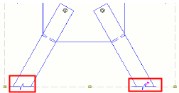
Example
Update cut part lines
- On the Sketching tab, click Cut part lines.
Tekla Structures removes all previously created cut part lines, and creates new ones that are up-to-date.
Update cut part lines
- On the Sketching tab, click Cut part lines.
Tekla Structures removes all previously created cut part lines, and creates new ones that are up-to-date.