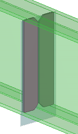
Example of a variable formula: Define the stiffener position using construction planes
This example shows how to use construction planes for defining the position of the stiffeners. You will position two stiffeners so that they divide the beam into three equally long sections.

-
To make it easier to select the
handles, ensure that
Direct modification
 is switched off.
-
On
the Custom component editor toolbar, click the Display variables
 button.
The Variables dialog opens.
-
Inquire the GUID of the beam:
-
In the Inquire object dialog, copy the beam's GUID.

-
In the Inquire object dialog, copy the beam's GUID.
-
Create a construction plane:
-
On the Custom component editor toolbar, click the Create construction plane
 button.
-
Click the middle mouse button to
create a construction plane at the center of a stiffener at one end.
-
On the Custom component editor toolbar, click the Create construction plane
-
Bind the stiffener to the construction plane:
-
Hold down
Alt and use area selection (from left to right) to select all stiffener handles.

-
Hold down
Alt and use area selection (from left to right) to select all stiffener handles.
-
Bind the construction plane to the beam end:
-
Bind the construction plane to the beam end.

-
Bind the construction plane to the beam end.
-
Select the custom component in
the model, and open the custom component dialog.
If you now change the beam length, the position of the stiffeners changes so that the stiffeners divide the beam into three equally long sections.
