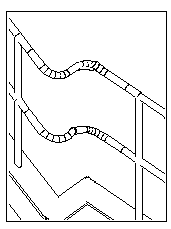
Railing double curve (95)
Railing double curve (95) connects the rail profiles of consecutive railings to each other. The rails have to reside so that the intersection is found.
Objects created
-
Railing profile
-
Welds
Use for
| Situation | Description |
|---|---|
|
|
Rail profiles of consecutive railings connected |
Selection order
-
Select the main part.
-
Select the secondary part.
The connection is created automatically when you select the secondary part.
Part identification key
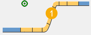
| Description | |
|---|---|
|
1 |
Railing profile |
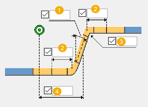
Picture tab
Use the Picture tab to control the geometry of the connection.
Dimensions
| Description | Default | |
|---|---|---|
|
1 |
Angle of the connecting beam. |
90 degrees |
|
2 |
The length of the straight part between the bend and the first beam or second beam, measured from the geometrical intersection of the beams. |
290 mm |
|
3 |
Bend radius of the curved parts. |
140 degrees |
|
4 |
Connecting beam position. The position is measured from the main part to the middle of the beam. |
Beam is placed in the middle of the parts. |
Parts tab
Use the Parts tab to define the part properties.
Parts
| Option | Description |
|---|---|
|
Profile |
Select the profile from the profile catalog. By default, the profile is the profile of the main part. |
|
Option |
Description |
Default |
|---|---|---|
|
Pos_No |
Prefix and start number for the part position number. Some components have a second row of fields where you can enter the assembly position number. |
The default part start number is defined in the Components settings in . |
|
Material |
Material grade. |
The default material is defined in the Part material box in the Components settings in . |
|
Name |
Name that is shown in drawings and reports. |
Parameters tab
Use the Parameters tab to define the method of construction for the connection.
Construction method
| Option | Description |
|---|---|
|
Create |
A new railing part is created to connect the main and secondary parts. This is the default option. |
|
Extend |
The railing is created as three tubes welded together. |
Fabricator name
Enter the fabricator name of the bend and the calculated additional beams.
General tab
Click the link below to find out more:
Analysis tab
Click the link below to find out more:
Welds
Click the link below to find out more: