Drawing weld mark properties
In drawing weld mark properties, you can view and modify the properties of a weld mark that has been manually added in a drawing.
Unlike model weld marks, drawing weld marks do not have an associated physical weld in the model, and you can only add drawing weld marks in an open drawing. For more information about welds and weld marks in drawings, see Show welds in drawings.
To open the drawing weld mark properties, do one of the following in an open drawing:
- Click a manually created drawing weld mark. If the property pane is not open, double-click the weld mark.
- Hold down Shift and click Weld mark on the Annotations tab.
- To open the drawing weld mark properties in a dialog, go to Quick Launch, start typing "weld mark" and select Weld mark properties from the displayed list.
|
Option |
Description |
|---|---|
| Save, load and search mark properties | 
|
| Mark | |
|
Edge/Around |
Indicate whether only one edge or the entire perimeter of a face should be welded. Edge: Around: |
|
Workshop/Site |
Indicate where the weld should be created. Workshop: Site: |
|
Stitch weld |
Set this option to Yes to create a staggered, intermittent weld. Stitch welds are staggered on both sides of the welded part. Tekla Structures shows the weld type symbols as staggered in weld symbols. If you set this option to No, a non-staggered intermittent weld is created. To show the pitch in a weld mark, set Pitch to a value greater than 0.0. |
|
Reference text |
Additional information to appear in the weld symbol. For example, information about the weld specification or process. |
|
Prefix |
a= design throat thickness, s= penetration throat thickness, or z= leg length |
|
Type |
The type of the weld. The following weld types are available:
For more information about model welds, see Create welds. You can customize some of the weld type symbols (symbols 20 - 26), see Customize weld type symbols for more information. |
|
Size |
The size of the weld. If you select a partial penetration weld as the weld type, you can enter two sizes. Partial penetration welds:
|
|
Angle |
The angle of weld preparation, bevels, or groove. Tekla Structures displays the angle between the weld type symbol and the fill type contour symbol. |
|
Contour |
The fill type contour of a weld can be: None
|
|
Finish |
Tekla Structures displays the finish symbol above the weld type symbol in drawings. The options are: G Grind M Machine C Chip
|
|
Effective throat |
The weld size used in weld strength calculation. |
|
Root opening |
The space between the welded parts. |
|
Length |
The length of a regular weld depends on the length of the connection between the welded parts. You can set the exact length of a polygon weld by defining the start and end points of the weld. |
|
Pitch |
The center-to-center spacing of welds for non-continuous welds. Pitch is shown in the weld mark if the value is greater than 0.0. To create a non-continuous weld, define the center-to-center spacing and the pitch of the welds. Tekla Structures calculates the distance between the welds as the pitch minus the length of the weld. By default, Tekla Structures uses the – character to separate weld length and pitch, for example, 50–100. To change the separator to @, for example, set the advanced option XS_WELD_LENGTH_CC_SEPARATOR_CHAR to @. |
|
|
Use these buttons to copy and to link together the Above line and Below line property values. Click the Click the The middle button is blue |
| Font | In Font color, Font, and Font height, define the drawing weld mark font properties. |
| Background |
Select Opaque to hide the part of the drawing that is covered by the mark. Select Transparent to show the part of the drawing that is covered by the mark, so that line work is visible, for example. |
| Leader line | |
| Line type, Line color |
Define the drawing weld mark leader line type and color.
|
| Placing | |
|
Placing method |
Free allows Tekla Structures to search for the first suitable location for the weld mark. Fixed allows you to place the weld mark in any location. When you use the option Fixed, the mark stays where it is even though you update the drawing, whereas with Free, Tekla Structures tries to find the optimal place for the weld mark. |
| Position |
Define the areas where Tekla Structures searches for a position to place the weld mark.
|
|
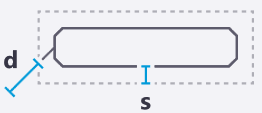
Distances |
Distance s is the empty margin that you want to leave around the mark. Distance d min is the minimum distance of the mark from the part. |
 .
.


 and
and  buttons to
copy values between the
buttons to
copy values between the  button to
switch the linking on or off.
button to
switch the linking on or off.  when the
values are linked. This means that if you change a value in
either of the columns, the corresponding value in the other
column also changes.
when the
values are linked. This means that if you change a value in
either of the columns, the corresponding value in the other
column also changes.