L-Profil Sockel Detail (1020)
L-Profil Sockel Detail (1020) fügt dem Träger- oder Stützenende ein Laschenprofil als Anschlussauflager hinzu.
Erzeugte Objekte
-
Pfettenschuh-Profil
-
Schrauben
-
Schweißnähte
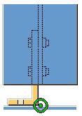
Verwendung
| Situation | Beschreibung |
|---|---|
|
|
Dem Trägerende wird ein Laschenprofil hinzugefügt. |

Auswahlreihenfolge
-
Wählen Sie das Hauptteil aus (Träger oder Stütze mit C- oder Verbund-C-Profil).
-
Wählen Sie eine Position auf dem Träger oder der Stütze aus.
Das Detail wird beim Picken der Position automatisch erstellt.
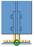
Teilerkennung
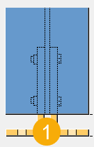
| Beschreibung | |
|---|---|
|
1 |
Pfettenschuh-Profil |
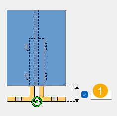
Registerkarte Abbildung
Auf der Registerkarte Abbildung definieren Sie den Abstand zwischen Laschenprofil und Hauptteil.
Abstand des Stollenprofils
| Beschreibung | Standardmäßig | |
|---|---|---|
|
1 |
Abstand zwischen der Unterkante Laschenprofil und Träger- oder der Stützenende. |
20 mm |
Registerkarte Teile
Auf der Registerkarte Teile können Sie die Eigenschaften für die Teile definieren.
Teil
| Option | Beschreibung | Standardmäßig |
|---|---|---|
|
Pfettenschuh-Profil |
Wählen Sie das Profil aus dem Profilkatalog aus. |
L 100*100*10 |
|
Option |
Beschreibung |
Standard |
|---|---|---|
|
Pos. Nr. |
Präfix und Startnummer für die Teilepositionsnummer. Einige Komponenten verfügen über eine zweite Feldreihe, in der Sie die Positionsnummer des Montageteils eingeben können. |
Die Standard-Teil-Startnummer wird in den Komponenten-Einstellungen unter festgelegt. |
|
Material |
Material. |
Das Standardmaterial wird im Feld Material der Teile in den Komponenten-Einstellungen unter festgelegt. |
|
Name |
Name, der in Zeichnungen und Listen angezeigt wird. |
Registerkarte Parameter
Auf der Registerkarte Parameter definieren Sie Position und Kantenabstand des Laschenprofils und ob Löcher oder Schrauben erstellt werden sollen.
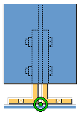
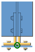
Lage des Pfettenschuhs
| Option | Beschreibung |
|---|---|
|
|
Standardmäßig Auf beiden Seiten werden Laschenprofile erstellt. AutoDefaults kann diese Option ändern. |
|
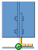
|
Auf der rechten Seite wird ein Laschenprofil erstellt. |
|
|
Auf der linken Seite wird ein Laschenprofil erstellt. |
Schrauben oder Löcher erstellen
| Option | Beschreibung |
|---|---|
|
|
Standardmäßig Im Auflagerschenkel des Laschenprofils werden Löcher erstellt. AutoDefaults kann diese Option ändern. |
|
|
Im Auflagerschenkel des Laschenprofils werden Schrauben erstellt. |
Pfettenschuhrandabstand
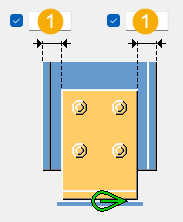
| Beschreibung | Standardmäßig | |
|---|---|---|
|
1 |
Abstand des Pfettenschuhs zum Rand des Träger- oder Stützenflanschs. |
Profilhöhe – 2 * (Flansch-T + r + 10 mm) |
Registerkarte Schrauben
Auf der Registerkarte Schrauben können Sie die Schraubengruppenabmessungen und die Schraubeneigenschaften definieren.
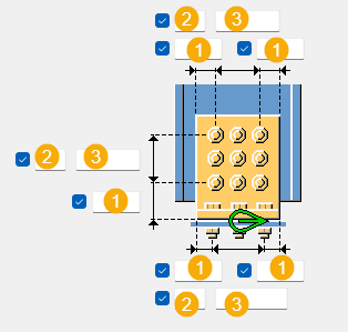
Maße Schraubengruppe
| Beschreibung | |
|---|---|
|
1 |
Schraubenrandabstand. Der Randabstand ist der Abstand zwischen der Mitte einer Schraube und dem Rand des Teils. |
|
2 |
Anzahl der Schrauben. |
|
3 |
Schraubenabstand. Geben Sie ein Leerzeichen ein, um Schraubenabstandswerte zu trennen. Geben Sie für jeden Schraubenabstand einen Wert ein. Geben Sie beispielsweise für 3 Schrauben 2 Werte ein. |
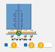
| Beschreibung | |
|---|---|
|
1 |
Schrauben in Auflager. Definieren Sie den Abstand zwischen der Rückseite des Pfettenschuhs und den Schrauben im Schenkel des Pfettenschuhs. |
|
2 |
Anzahl der Schrauben. |
|
3 |
Schraubenabstand. Geben Sie ein Leerzeichen ein, um Schraubenabstandswerte zu trennen. Geben Sie für jeden Schraubenabstand einen Wert ein. Geben Sie beispielsweise für 3 Schrauben 2 Werte ein. |
Grundlegende Schraubeneigenschaften
|
Option |
Beschreibung |
Standard |
|---|---|---|
|
Durchmesser |
Schraubendurchmesser. |
Die verfügbaren Größen sind im Schraubengarniturkatalog definiert. |
|
Schraubennorm |
Die innerhalb der Komponente zu verwendende Schraubennorm. |
Die verfügbaren Normen sind im Schraubengarniturkatalog definiert. |
|
Lochspiel |
Das Spiel zwischen Schraube und Loch. |
|
|
Gew. im Material |
Legt fest, ob sich das Gewinde bei Schaftschrauben innerhalb der verschraubten Teile befinden darf. Dies hat keine Auswirkungen, wenn Vollgewindeschrauben verwendet werden. |
Ja |
Schnittlänge
Legt die Tiefe fest, in der Tekla Structures nach den Querschnitten der verschraubten Teile sucht. Damit können Sie bestimmen, ob die Schraube einen oder zwei Flansche verbindet.
Verschraubungsrichtung
|
Option |
Beschreibung |
|---|---|
|
|
Standard Schraubenrichtung 1 AutoDefaults kann diese Option ändern. |
|
|
Verschraubungsrichtung 1 |
|
|
Verschraubungsrichtung 2 |


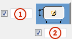
Langlöcher
Es können Langlöcher oder überdimensionierte Löcher definiert werden.
| Option | Beschreibung | Standardmäßig |
|---|---|---|
|
1 |
Vertikale Abmessung des Langlochs. |
0 ergibt ein rundes Loch. |
|
2 |
Horizontale Abmessung des Langlochs oder Größe für übergroße Löcher. |
0 ergibt ein rundes Loch. |
|
Lochtyp |
Langloch erstellt Langlöcher. Großes Loch erstellt überdimensionierte Löcher. Kein Loch erzeugt keine Löcher. Gewindelöcher erstellt Gewindelöcher. |
|
|
Gedrehte Löcher |
Wenn es sich bei dem Lochtyp um Langloch handelt, werden die Langlöcher mit dieser Option gedreht. |
Schraubengarnitur
Die aktivierten Kontrollkästchen definieren, welche Objekte (Schrauben, Unterlegscheiben und Muttern) in der Schraubengarnitur verwendet werden.
Deaktivieren Sie alle Kontrollkästchen, wenn Sie nur ein Loch erstellen möchten.
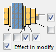
Um die Schraubengarnitur in einer vorhandenen Komponente zu ändern, aktivieren Sie das Kontrollkästchen Änderung und klicken auf Ändern.
Verlängerung der Schrauben
Definieren Sie, um welches Maß die Schrauben verlängert werden sollen. Verwenden Sie diese Option zum Beispiel dann, wenn eine Verlängerung der Schrauben aufgrund einer Lackierung erforderlich wird.

Registerkarte Allgemein
Klicken Sie auf den folgenden Link, um weitere Informationen zu erhalten:
Registerkarte Berechnung
Klicken Sie auf den folgenden Link, um weitere Informationen zu erhalten:
Schweißnähte
Klicken Sie auf den folgenden Link, um weitere Informationen zu erhalten: