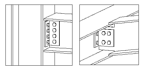
Angle cleat (3)
Angle cleat (3) connects two beams or a beam to a column using one or two bolted clip angles.
Objects created
-
Clip angle (L profile)
-
Bolts
-
Welds
Use for
| Situation | Description |
|---|---|
|
|
Clip angle bolted between the parts. The secondary part can be sloped. |
Selection order
-
Select the main part.
-
Select the secondary part.
The connection is created automatically when the secondary part is selected.
Part identification key
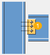
| Description | |
|---|---|
|
1 |
Clip angle |
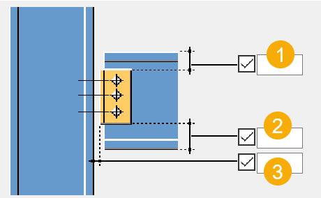
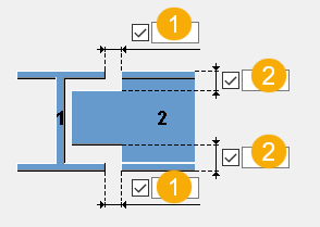
Picture tab
Use the Picture tab to define the clip angle length, and the gap between the main part and the clip angle.
Dimensions
| Description | |
|---|---|
|
1 |
Clip angle edge distance from the secondary part upper edge. You can control the clip angle length by defining the distance from the secondary part upper and lower edge. |
|
2 |
Clip angle edge distance from the secondary part lower edge. |
|
3 |
Gap between the main part and the clip angle. By default, the value is 0. |
Parts tab
Use the Parts tab to define the clip angle properties.
Parts
| Option | Description | Default |
|---|---|---|
|
L profile |
Select the profile from the profile catalog. |
L150-100-10 |
|
Option |
Description |
Default |
|---|---|---|
|
Pos_No |
Prefix and start number for the part position number. Some components have a second row of fields where you can enter the assembly position number. |
The default part start number is defined in the Components settings in . |
|
Material |
Material grade. |
The default material is defined in the Part material box in the Components settings in . |
|
Name |
Name that is shown in drawings and reports. |
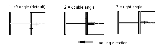
Parameters tab
Use the Parameters tab to define the location of the clip angles.
Placing
| Option | Description |
|---|---|
|
Placing |
By default, the clip angle is created on the left side. Middle creates two clip angles. |
Notch tab
Use the Notch tab to define the secondary part notch dimensions.
Cut dimensions
| Description | ||
|---|---|---|
|
1 |
Dimension for the horizontal flange cut. |
10 mm |
|
2 |
Dimension for the vertical flange cut. |
The gap between the notch edge and the beam flange is equal to the main part web rounding. The notch height is rounded up to the nearest 5 mm. |
General tab
Click the link below to find out more:
Design tab
Click the link below to find out more:
Analysis tab
Click the link below to find out more:
Bolts
Click the link below to find out more:
Welds
Click the link below to find out more: