Bridging (80)
Bridging (80) creates bridging elements for cold rolled profiles. You can use any work plane when creating Bridging (80).
Objects created
-
Bridging
-
Start clip
-
End clip
Use for
| Situation | Description |
|---|---|
|
|
Bridging is created. |

Selection order
-
Select the first rafter.
-
Select the second rafter.
-
Select the first purlin.
-
Select the remaining purlins in one direction only.
-
Click the middle mouse button to create the bridging.
Part identification key
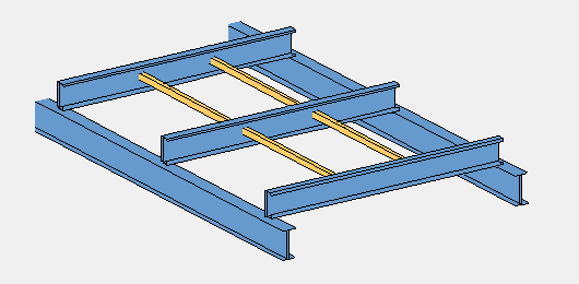
Picture tab
The Picture tab shows an example of the bridging.
Bridging
Parts tab
Use the Parts tab to define the part properties for the bridging, start clip, and end clip.
Properties
|
Option |
Description |
Default |
|---|---|---|
|
Pos_No |
Prefix and start number for the part position number. Some components have a second row of fields where you can enter the assembly position number. |
The default part start number is defined in the Components settings in . |
|
Material |
Material grade. |
The default material is defined in the Part material box in the Components settings in . |
|
Name |
Name that is shown in drawings and reports. |
|
|
Class |
Part class number. |
|
|
Finish |
Describes how the part surface has been treated. |
Parameters tab
Use the Parameters tab to define the type and location of the bridging elements.
The component always starts and ends a bridging run with a bolted connection.
| Option | Description |
|---|---|
|
Bridging type |
Select the briding type. |
|
State of use |
Set this value even if you have selected to use the Automatic bridging type option. |
|
Start bridge code Intermediate bridge code End brigde code |
Enter the bridging codes for manual bridging types. |
|
Number of rows |
Define the number and location of the rows of bridging elements.
|
|
Custom spacing |
Enter percentage values for custom spacing between the rafters, for example: 0.25 0.5 0.75. If custom spacing is not defined, the longest purlin is used as the base length for spacing. |
|
Purlin type |
If you did not select the Custom option in Number of rows, select an option from the list to define the purlin type. |
|
Purlin location |
If you did not select the Custom option in Number of rows, select an option from the list to define the purlin location. |
|
Bridging spacing |
Select whether spacing is done based on the longest purlin or the selected rafters. |
Bolts tab
Use the Bolts tab to define the bolt group dimensions and bolt properties for start and end bolts.
Bolt properties
| Option | Description |
|---|---|
|
Read from |
Select whether to use bolt properties from a data file or from the dialog. By default, the data file is used. |
|
Use different bolt settings |
Select to use different bolt properties for the start and end bolts. |
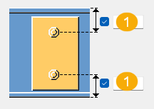
Bolt group dimensions
| Description | |
|---|---|
|
1 |
Bolt edge distance. Edge distance is the distance from the center of a bolt to the edge of the part. |
Bolt basic properties
|
Option |
Description |
Default |
|---|---|---|
|
Bolt size |
Bolt diameter. |
Available sizes are defined in the bolt assembly catalog. |
|
Bolt standard |
Bolt standard to be used inside the component. |
Available standards are defined in the bolt assembly catalog. |
|
Tolerance |
Gap between the bolt and the hole. |
|
|
Thread in mat |
Defines whether the thread may be within the bolted parts when bolts are used with a shaft. This has no effect when full-threaded bolts are used. |
Yes |
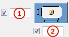
Slotted holes
You can define slotted, oversized, or tapped holes.
|
Option |
Description |
Default |
|---|---|---|
|
1 |
Vertical dimension of slotted hole. |
0, which results in a round hole. |
|
2 |
Horizontal dimension of slotted hole, or allowance for oversized holes. |
0, which results in a round hole. |
|
Hole type |
Slotted creates slotted holes. Oversized creates oversized holes. No hole does not create holes. Tapped creates tapped holes. |
|
|
Rotate Slots |
When the hole type is Slotted, this option rotates the slotted holes. |
|
|
Slots in |
Part(s) in which slotted holes are created. The options depend on the component in question. |
Data files used by Bridging (S80)
For the Australasia environment, ensure that the following data files are located in the ...\Environments\Australasia\General\profil\cr\ folder:
-
overlap.dat
-
brioc.dat
-
brnam.dat
overlap.dat file
This file contains information about the purlin profiles. Each row contains information about a specific purlin and the columns define the properties described in the table below.
| Column | Description |
|---|---|
|
1 |
The exact name of the profile used for the purlin in the model |
|
3 |
Bolt standard. Defined in the bolt assembly catalog. |
|
4 |
Bolt size. Defined in the bolt assembly catalog. |
|
Gap between the bolt and the hole |
|
|
6 |
Dimension of the slotted hole in the X direction. For no slotted holes, set to zero. |
|
7 |
Dimension of the slotted hole in the Y direction. For no slotted holes, set to zero. |
|
9 |
Indicates if the thread can be inside bolted parts when using bolts with a shaft. This has no effect if full-threaded bolts are used. 0 – No 1 – Yes |
|
12 |
Vertical distance between bolts |
brloc.dat file
This file contains information about the location of bridging profiles. Each row contains information about a specific bridging type and the columns define the properties described in the table below.
| Column | Description |
|---|---|
|
1 |
Bridging type |
|
2 |
Purlin type: Simple, Continuous, or Lapped. |
|
3 |
The type of span where the bridging elements are located:
|
|
4 |
Span ratio for 1 row of bridging |
|
5 |
Span ratio for the first row of bridging if there are two rows of bridging |
|
6 |
Span ratio for the second row of bridging if there are two rows of bridging |
|
7 |
Span ratio for the first row of bridging if there are three rows of bridging |
|
8 |
Span ratio for the second row of bridging if there are three rows of bridging |
|
9 |
Span ratio for the third row of bridging if there are three rows of bridging |
Span ratio values are cumulative and must be numbers between 0 and 1.
brnam.dat file
This file contains the names of bridging elements and cleats, comments and information about clip bolts. Each row defines a specific bridging type and the columns define the properties described in the table below.
When selecting the
Bridging type on the Parameters
tab, use the Automatic option to have Tekla Structures calculate the bridging type using the brnam.dat file. This is the default option. The option
searches for the first line that contains the correct profile name. If this line
is in the BHP block, the component uses the
purlin height to determine the bridging type. If the line is not in the BHP block, the component selects the bridging type that
appears in the first column.
| Column | Description |
|---|---|
|
1 |
Bridging type |
|
2 |
Name of the purlin profile in the model |
|
3 |
Name of the bridging profile in the model |
|
4 |
Name of the clip profile in the model |
|
7 |
Comment for the first clip. To not create a start clip, set to None. |
|
8 |
Comment for
the first bridging element if |
|
9 |
Comment for
the start bridging element if |
|
10 |
Comment for the interior bridging elements |
|
11 |
Comment for
the end bridging element if |
|
12 |
Comment for
the end bridging element if |
|
13 |
Comment for the fascia bridging element |
|
14 |
Comment for the end clip. To not create an end clip, set to None. |
|
15 |
Bolt hole properties for the start clip, XY. Enter a two-digit number to set the bolt hole settings for start clips. X
Y
|
|
16 |
Bolt hole properties for interior clips, XY. Enter a two-digit number to set the bolt hole settings for interior clips. X
Y
|
|
17 |
Bolt hole properties for the end clip, XY. Enter a two-digit number to set the bolt hole settings for end clips. X
Y
|