Tekla Structural Designer into Autodesk Revit
Creation of the Tekla Structural Designer Model
The Engineer has a number of options available to him when creating a Tekla Structural Designer model.
Create a model from scratch
-
Tekla Structural Designer includes typical modeling tools to create grids, columns, beams, walls, floors etc. Importantly each element is modeled as a physical object which can be positioned correctly in space.
-
When synchronized with Autodesk Revit, the true spatial position is communicated along with items such as sections size, grade, studs, holes etc.
-
For a full list of communicated items, see Information transferred.
Part Models
-
At the early stages of design it is possible to create part models to investigate a structural scheme.
-
For example the engineer can model just a floor or a bay in Tekla Structural Designer to investigate the best solution to satisfy code compliance and economics.
-
Although only a part model, this can still be sent to Autodesk Revit. (Note, the physical position of the part model will be communicated to Autodesk Revit.)
-
For example, if an engineer models a floor but the true level is not yet known, this part model can be sent to Autodesk Revit where adjustments can be made. If this model is communicated back to Tekla Structural Designer its position will be updated.
-
At the early design stages is it reasonable to stop the bi-directional integration as new refined models are often created later in the design process.
Import 2D Drawings
-
It is common early in a project to have a number of 2D architectural drawings outlining the scheme. Tekla Structural Designer has the facility to import 2D DXF drawings.
-
The engineer can use these drawings as ghost layouts in the background to aid setting out or to import grids.
-
If a common grid is used on the project, it is logical to import this grid into Tekla Structural Designer to ensure the structure is set out in the correct position.
-
If a number of separate models are to be created and merged together it is strongly advisable to use a common grid system.
-
When importing grids it is also advisable to check the geometry of the grid thoroughly.
Deliverables
Even at these early stages of a project, Tekla Structural Designer provides a significant number of the deliverables required.
For example :-
-
Comprehensive code compliant scheme design
-
Material take off
-
2D engineering DXF drawings
-
Member end forces and support reactions
Exporting a model from Tekla Structural Designer
Once a model has been created in Tekla Structural Designer, you need to save the model with a recognisable name and then run the command Autodesk Revit Export (BIM Integration tab).
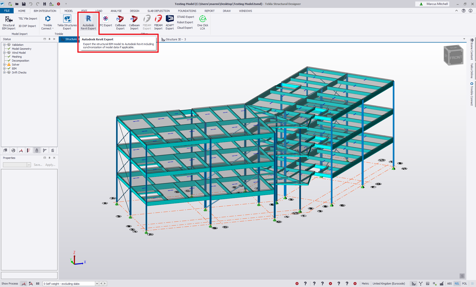
Running the command will start the export application with various dialogs displayed through a wizard process.
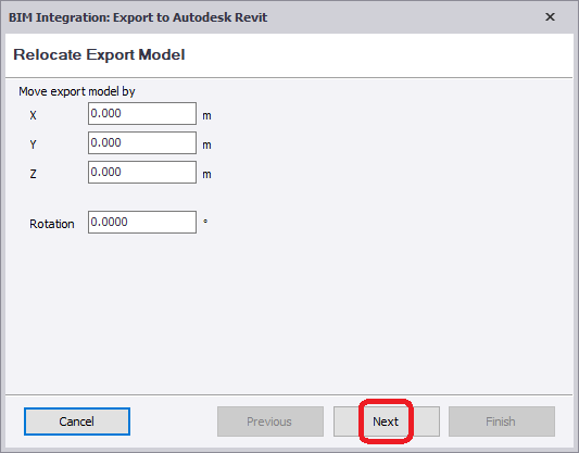
The first screen encountered will allow you to move the model to real world coordinates by entering suitable figures within the dialog. In our case, we will keep the values at the default and just choose Next.
After the model location, you will be prompted to choose the element types to choose to export along with options for openings where applicable. The default settings are that all items should be exported. In this example, we will follow the same settings and export all object types – clicking Next to continue.
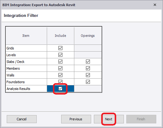
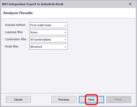
In this example, we have chosen to export Analysis Results as the model has been successfully analyzed and designed within Tekla Structural Designer. This option (deselected as default) directs us to a new dialog where we can choose which analysis methods, loadcase results and load combination results we can choose to export. We keep the default setting of first order linear analysis results for all combinations and simply click on the Next button to advance.
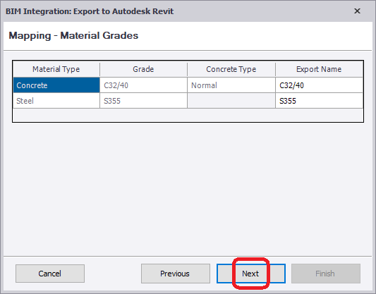
Mapping of materials to recognized grades will be then shown. Here you can view the different materials being used in the Tekla Structural Designer model and the option to overwrite the exported materials with a more preferred grade.
Following on from Material mapping, the dialog for Decking mapping will be shown (if applicable). Again this allows users to view the decking types being used in the model and have the option of overwriting the exported details if required.
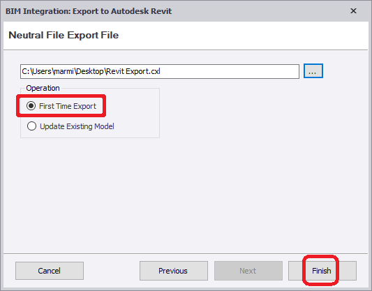
The final dialog screen of the export wizard will prompt for a filename and location of the CXL file to be created. Please note that there are two options relating to a First Time Export and an option to Update Existing Model.
For the initial export, the option First Time Export should be chosen. (The option to Update Existing Model will be used to pass alterations in the event of a Autodesk Revit model already in existence.)
Importing a model from Tekla Structural Designer to Autodesk Revit
This example covers the import of a correct model into Autodesk Revit using the Tekla Structural Designer Integrator for Autodesk Revit software.
Note : The file that we are using contains no mapping problems and reference should be made to the relevant sections should you find that your own file does have any problems regarding mapping.
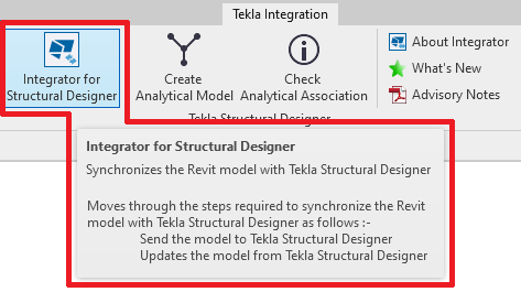
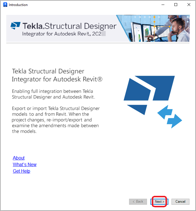
Firstly, activate the Integrator program by clicking on the Integrator for Structural Designer icon held on the Tekla Integration tab.
The initial splash screen provides some information about the Integrator along with hyperlinks to the relevant website page and links to useful information. Click Next to move onto the next page.
The next dialog of the Integrator allows import and export options to be set.
At this stage, the integrator checks the active Revit model for any instances containing Tekla Structural Designer data, indicating prior data exchange. If any elements are found, the First time import option is automatically disabled forcing the Update existing model option to be used instead.
In this example though, we are importing a file created from Tekla Structural Designer and we do not currently hold a Revit model to synchronize into. We can therefore choose the option Import model into Revit - First time import.
Click Next to continue after making your selection.

Having chosen the software and the correct import/export option, you will be prompted to select the file (and location) that you wish to import.
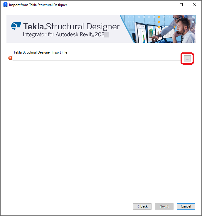
Select the correct information and then click Next to move onto the next dialog.

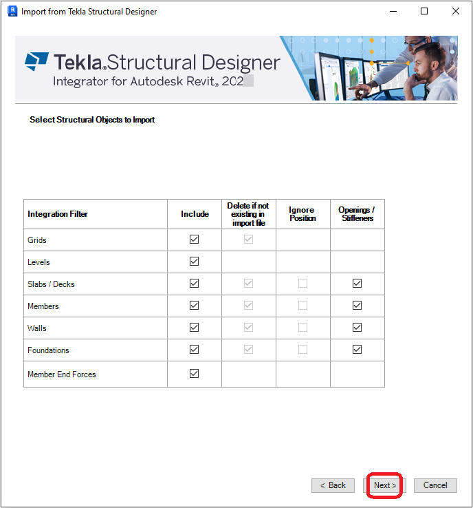
The Select Structural Objects to Import dialog allows you to control which items will be imported into Autodesk Revit. As a default the application will automatically flag items for inclusion in the import, but if you have a requirement to omit certain items (say Grids), then simply untick the item option.
Any grayed box may not be altered in its setting. This is to simply inform the user that these styles of objects or options will either be included (if ticked) or omitted (unticked).
Member End Forces will always be deselected as a default. Select this option if forces are required for import.
Member End Forces can be included in an import if a valid (designed) Tekla Structural Designer model was exported. If a Tekla Structural Designer model was exported before the design was completed, no member end forces will be included in the CXL file.
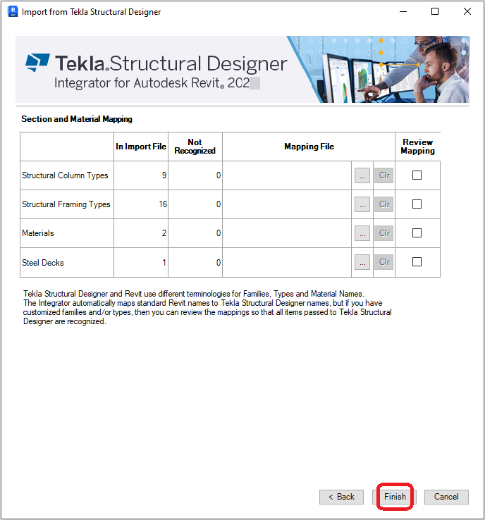
The Section and Material Mapping dialog indicates the different section families detected in the importing file. If there are any numerical entries in the Not Recognized column then there are some mapping discrepancies, these should be investigated before continuing further. (See separate section on mapping objects).
Even if the mapping is correct and no problems exist (as per the example shown in the screenshots), the actual mapping can be checked by clicking to select the Review Mapping option for all Columns, Framing, Materials and Steel Decks.
Click Finish to exit from the Integrator dialog and start the processing of the file.
Having completed the use of the Integrator dialog, the importing CXL file will now start processing. This is a stage that is run automatically by the application and covers the actual building of the model, loading the correct families, assigning shared parameter data to members etc.
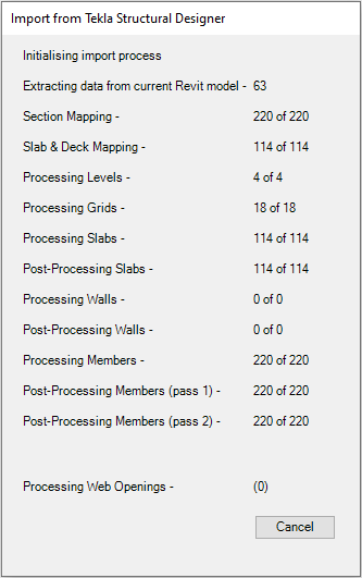
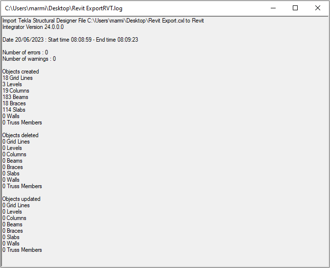
Once the processing of the CXL file has been completed, a log file will be shown. The log file is simply a text file and a record of the objects imported, deleted or altered along with any warnings.
Please note that the log file is automatically saved into the same directory location used for the CXL file location (although this can be manually moved at a later date).
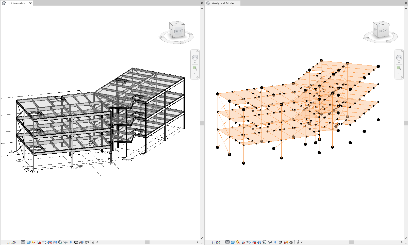
Created analytical model
Please note that as part of the overall import process, the analytical model will be automatically created for all instances imported from Tekla Structural Designer. These will be built using the same locations (and any relevant offset values) as stipulated by the Tekla Structural Designer model.