Seismic drift check
Overview
Using a method (referred to below as Every Column/Wall Stack), seismic drift can be calculated for all columns of all materials, and all walls at every level in the model for whichever seismic loading design code has been selected.
If working to ASCE 7 two additional methods are also provided: Automatic - Center of Mass and Automatic - Edge of Structure.
In all methods the seismic stability coefficient θ in each direction is checked against the limit θmax and then the stack design story drift Δdes is determined in each direction and checked against the allowable story drift Δa
Summary results are presented in terms of levels, and if required, detailed results can also be obtained.
For levels set as floors a "Reporting Level" option is available in Level Properties. By unselecting this option, individual levels can be excluded from the check reporting.
Understanding the Every Column/Wall Stack method
This method is available for all versions of the Seismic Wizard.
For each seismic combination, for a given stack, the design story drift in Dir1 and Dir2 is determined using the elastic analysis results.
For each seismic combination, for each stack, for each direction; the check passes provided the stack design story drift doesn't exceed the allowable story drift, Δa.
If using US codes:
Dir1 stack design story drift, ΔdesDir1i ≤ Δa
Dir2 stack design story drift, ΔdesDir2i ≤ Δa
Where, if risk category I or II
- Δa = 0.020 × hsx
If risk category III
-
Δa = 0.015 × hsx
If risk category IV
-
Δa = 0.010 × hsx
Where hsx is the story height associated with the story drift.
Note that for SDC = D, E or F if the structure has only moment frames (no braces, no shear walls) then Δa / ρ is used instead of Δa, where ρ is the redundancy factor.
If using the Eurocode (EN 1998-1):
Dir1 stack design story drift, Δdes_Dir1_i ≤ Δa
Dir2 stack design story drift, Δdes_Dir2_i ≤ Δa
Δa = Story drift factor × h / V
Where:
h is the story height associated with the story drift
Story drift factor is:
- 0.005 for non structural elements of brittle material
- 0.0075 for ductile non structural elements
- 0.010 for unconnected or no non structural elements
V is
- 0.5 for Importance Class I or II
- 0.4 for Importance Class III or IV
If using the Indian code (IS1893):
Dir1 stack design story drift, Δdes_Dir1_i ≤ Δa
Dir2 stack design story drift, Δdes_Dir2_i ≤ Δa
Δa = factor × h
Where:
h is the story height associated with the story drift
factor is 0.004 as per IS1893:2002 cl. 7.11.1
Understanding the Automatic - Center of Mass method
This method is only available when using the Seismic wizard (ASCE 7).
It can be selected from the Localization page of the wizard provided there are no plan 1 irregularities, or if there are plan 1 irregularities and the SDC is category B.
For new structures it is the default method when the above conditions are met.
When using this method, the Torsional Irregularity Ratio (TIR) is calculated for the building and reported in the Seismic Report against the Plan 1 Irregularity.
In the same way as the "Every Column/Wall Stack" method the stack design story drift is checked to ensure it doesn't exceed the allowable story drift, Δa. The only difference being that the stack design story drift is calculated at the center of mass of the diaphragm located at the co-ordinates indicated at the top of the calculation.
This method is best suited to models with one diaphragm per level. In models with complexities, such as multiple diaphragms per level, mis-aligned diaphragms between levels, etc this option tends to generate warnings. When warnings are issued you should consider swapping to the “Every Column/Wall Stack” method.
Understanding the Automatic - Edge of Structure method
This method is only available when using the Seismic wizard (ASCE 7).
It can be only be selected from the Localization page of the wizard if there are plan 1 irregularities and the SDC is category C, D, E or F.
For new structures it is the default method when the above conditions are met.
When using this method, the Torsional Irregularity Ratio (TIR) is calculated for the building and reported in the Seismic Report against the Plan 1 Irregularity.
In a similar way to the "Every Column/Wall Stack" method, the stack design story drift is checked to ensure it doesn't exceed the allowable story drift, Δa.
The differences between this and the “Every Column/Wall Stack” method are:
- It only considers members attached to the edges of diaphragms.
- Members not attached to any diaphragm are not considered, (you should ensure you are comfortable with this).
- It automatically finds the worst result from all such members - in most normal circumstances there are exactly the same results as would be found by the “Every Column/Wall Stack” method.
- The advantage of the "Edge of Structure" method is that the results are more concise, with all the detailed results found in a single results dialog.
Configure the check and set the limit
The check is configured on the Localization page of the The seismic wizard.
An option is provided to override the allowable story drift factor and a second option allows for the seismic drift check to be skipped entirely if required.
If working to the ASCE 7 code this page also allows you to select the approach to use as either:
- Automatic - Center of Mass/Edge of Structure*
- Every Column/Wall Stack
* If there are no plan 1 irregularities, or if there are plan 1 irregularities and the SDC is category B, seismic drift is calculated at the center of mass; if there are plan 1 irregularities and the SDC is category C,D, E or F, it is calculated at the edge of structure.
Run the check
Seismic load combinations are automatically checked on a level by level basis for seismic drift by running an appropriate analysis or design.
Review the check status and details
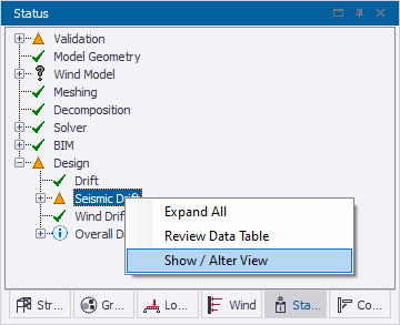
Once the check has been run, an overall status is reported in the Design branch of the Status Tree, the overall status being the worst status from each of the individual levels.
Right clicking on the status opens a context menu.
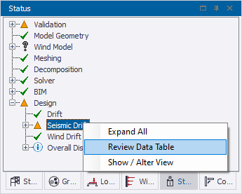
From this menu you can display the seismic drift check summary in a Review Data Table.
The table that gets displayed will depend on the method being used:
-
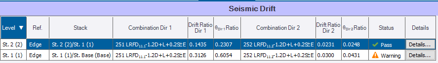
If using the Every Column/Wall Stack approach the table will be laid out as shown below:
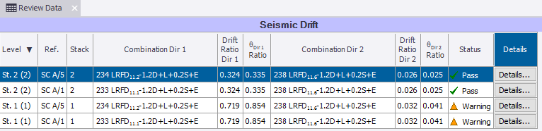
In the summary, either one or two rows of results are output for each level; when two rows are output the critical drift ratio in Dir 1 is given in one row, and the critical drift ratio in Dir 2 in the other, (for completeness of the table, in each row the value in the other direction is also shown even though it might not be critical).
By unselecting the Summary Only option in the ribbon, the table can also display detailed results on a stack by stack basis if required.

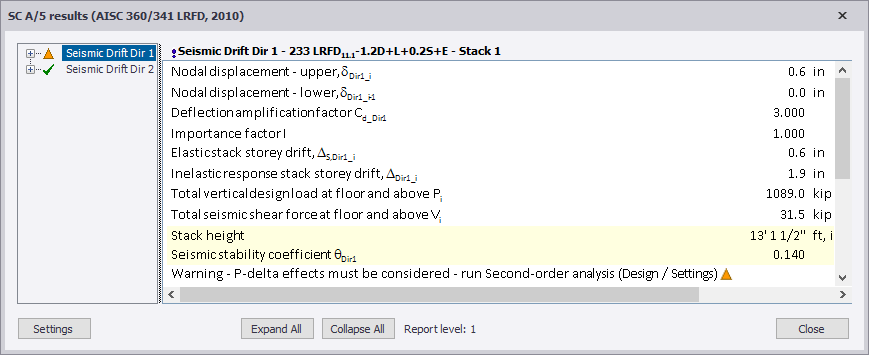
The individual stack by stack checks can be investigated in more detail by clicking the Details button at the end of any row.
-
If using the Automatic - Center of Mass approach the table will be laid out as shown below:
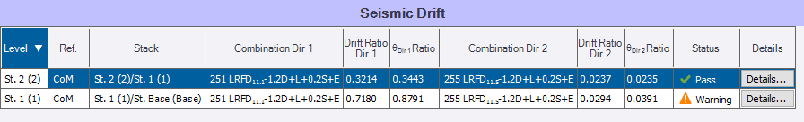
A single row of results is output for each level displaying the critical drift ratio in Dir 1 and Dir 2.
There is only a summary version of the table so unselecting Summary Only in the ribbon has no effect.
The calculations can be investigated in more detail by clicking the Details button at the end of any row.
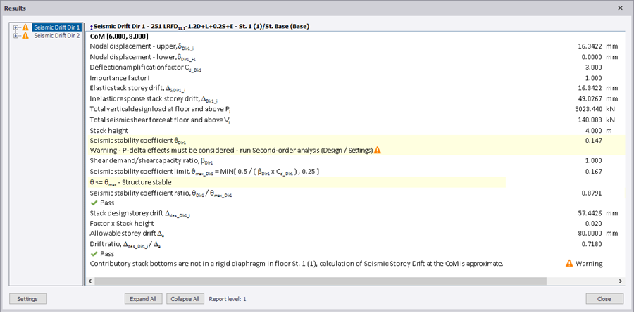
At the top of the details the co-ordinates of the center of mass are displayed, this is useful if there are multiple diaphragms, as it tells you which CoM was actually used in the calculation.
-
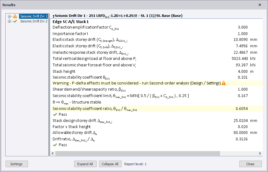
If using the Automatic - Edge of Structure approach the table will be laid out as shown below:
A single row of results is output for each level displaying the critical drift ratio in Dir 1 and Dir 2.
There is only a summary version of the table so unselecting Summary Only in the ribbon has no effect.
The calculations can be investigated in more detail by clicking the Details button at the end of any row.
Review the check graphically
From the right click menu in the Status Tree you are also provided with an option to graphically review the checks in a Show/Alter State View. Currently this is only meaningful for the "Every Column/Wall Stack" approach.
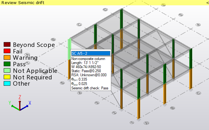
The color coded legend makes it easy to see individual failing members. By hovering the cursor over a member, its seismic drift results are displayed in the tooltip.
From the same Show/Alter State view, by changing the Mode in the Properties window, you also have the option to switch off checks for specific stacks if you require.
Switching off inappropriate checks and merging stack lengths
After reviewing you might choose to switch off checks for selected columns and walls, or individual stacks/panels within selected columns and walls: this can be done directly via the Properties window, or graphically in a Show/Alter State view (as described in the previous section).
You might also choose to take advantage of the option to merge short stacks automatically where they are less than a specified limit. Stacks check lengths can also be be manually adjusted by merging them together if required.
An option is also provided which allows you to switch off checks for specific levels if you decide they are inappropriate, (for example if the story height is very short). The checks at that level are still performed, but they are excluded from the tabular review data display.
Printing calculations
The seismic drift check results table is available either by creating a Seismic Design report, or by including the Analysis>Seismic Drift chapter in a custom report.