Masonry wall design - introduction
Masonry walls can be modeled and analyzed in Tekla Structural Designer for all regional codes.
For the US regional code, Tekla Tedds can be used to automatically define material and analytical properties, as well as to perform the design of the masonry wall sections. Patches associated with a masonry wall panel are checked as part of the panel design and can also be investigated independently in Tekla Tedds from within Tekla Structural Designer.
In the current release there is no particular consideration in modeling, analysis or design, for any other type of masonry wall other than single pane, in-plane loaded masonry walls (typically internal).
Wall types
- clay masonry - solid, hollow, filled, or partially filled
- concrete masonry - solid, hollow, filled, or partially filled
- unreinforced, or reinforced (vertical and horizontal)
- single skin walls only, double skin walls (i.e. using two layers of masonry) are beyond scope.
Reinforcement
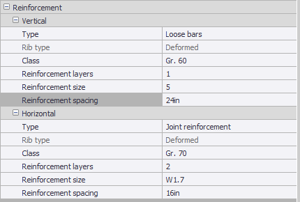
Reinforcement data is specified in the masonry wall Properties window. It can be assigned to the wall in two types of arrangement - vertical and horizontal.
If vertical reinforcement is set to None, you are prevented from specifying horizontal reinforcement.
You have control over the reinforcement type, class, layers, size and spacing for each arrangement.

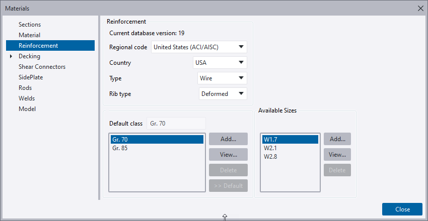
Vertical reinforcement can only be in the form of loose bars, while horizontal reinforcement can be in the form of bond beams or joint reinforcement. Bond beams use loose bars from the Tekla Structural Designer database while joint reinforcement uses 'Wire' reinforcement included in the database specifically for this purpose.

Wall patches
Wall patches are local design areas within masonry wall panels where local effects can be considered and unique grout and reinforcement can be designed within a wall panel. This is particularly useful for wall panels with openings, but can be used to design for local load effects as well.
Each wall patch automatically generates a group of horizontal result lines; a user specified number of result lines plus additional result lines at points of interest (at tops and bottoms of openings). Each result line collects the cross section forces at its location.
The default creation mode, Quick patch, will create full height wall patches between openings with a single click; other creation options provide more flexibility in definition. Once defined, the bounds of a wall patch can be easily modified.
Accepting the default settings begins a workflow where the grout and reinforcement is uniform across the whole panel in the final design and local forces in the wall patches are checked against that uniform construction. The wall patch areas are set to “as panel”, linking the wall patch grout and reinforcement definitions to the parent wall panel:
-
Define the wall construction, grout and reinforcement for each wall panel in Tekla Structural Designer. The Check in Tedds button on the Design ribbon will check the design of all defined wall panels and patches and return design results to review.
-
If the design fails at some patch locations then you adjust the wall properties (more grouting and/or more reinforcement) to achieve a pass.
-
Grout spacing must be changed in Tekla Structural Designer - reinforcement may be changed from Tekla Structural Designer or during interactive design in Tedds
-
Changes to grout or reinforcement spacing to a wall panel or wall patch while the property is set to “as panel” will update the parent panel and all other patches that are set to “as panel”
-
-
Note that by restricting patches to the extent of the area between openings you might avoid some over-design - see Advanced knowledge below.
-
Note that design of narrow patches can be beyond scope - see Advanced knowledge below.
When uniform wall construction does not meet design requirement, wall patches can be used to define and design localized strengthening in the wall patch area:
-
Simply uncheck the required “as panel” setting and then define grouting and/or reinforcement that will be specific to that patch area.
-
Check or Design in Tedds commands for a wall panel will execute the same process for all wall patches within a panel and return design results to review.
-
This may allow design of some narrower patches - see Advanced knowledge below.
-
A single design length is used for all the check positions:
-
Design Length = Min Result Length for any Result line in the patch.
-
It's also limited to a maximum of patch width (It would be potentially unconservative to allow it to be greater than this since this is the maximum width where local strengthening can be assumed to be effective)
-
-
Potential for over design:
-
Result lines within a patch can all be capturing results for different result lengths.
-
IF the max length = 6’ and the min = 3’, then the design length = 3’ but the design will consider forces that were captured from a 6’ length. Clearly that has the potential to be over conservative, but note that
-
This example is extreme - it would be unusual for the lengths to vary this much
-
The shorter lengths are usually the zones between openings/edges where load is more concentrated - so the highest load may still come from the shortest length.
-
-
Extreme length variation might be reduced by using a finer FE mesh
-
In the case of “as panel” patches the extent of the patch might be reduced to focus on the area between points of interest.
-
E.g. limit to just the height of the openings where patch is being added.
-
-
-
Narrow Patches:
-
(Tedds) Design is beyond scope if the design length <
-
Masonry Unit Length
-
Grout Spacing
-
Vertical Reinforcement Spacing
-
-
In the situation where reinforcement or grout spacing in the panel is greater than a patch width then you can design the patch for a locally reduced spacing.
-
Design codes
- TMS MSJC 2013
- TMS 402/602 2016
- TMS 402/602 2022