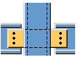
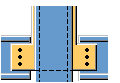
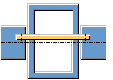
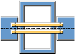
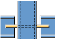
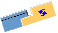
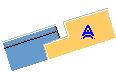
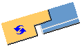
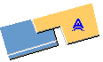
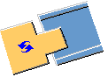
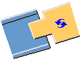
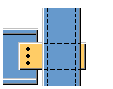
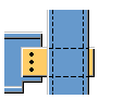
Shear plate to tube column (47)
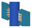
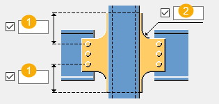
Shear plate to tube column (47) connects two beams to a tube column with a shear tab. The shear tab goes through the tube column.
Objects created
-
Shear tab
-
Bolts
-
Welds
Use for
| Situation | Description |
|---|---|
|
|
Two beams connected to a tube column with a shear tab |
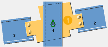
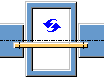
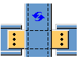
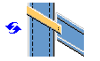
Selection order
-
Select the main part (column).
-
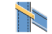
Select the first secondary part (beam).
-
Select the second secondary part (beam).
-
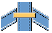
Click the middle mouse button to create the connection.
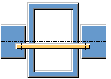
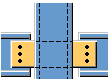
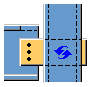
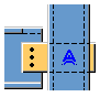
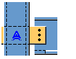
Part identification key
| Description | |
|---|---|
|
1 |
Shear tab |
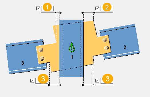
Picture tab
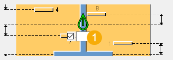
Use the Picture tab to define the shear tab position.
Dimensions
| Description | |
|---|---|
|
1 |
Distance from the edge of the main part to the notched shear tab corner at the top |
|
2 |
Distance from the edge of the main part to the shear tab top corner |
|
3 |
Distance from the edge of the main part to the notched shear tab corner at the bottom |
Parts tab
Use the Parts tab to define the shear tab properties.
Parts
| Parts | Description |
|---|---|
|
Shear plate |
Thickness of the shear tab |
|
Option |
Description |
Default |
|---|---|---|
|
Pos_No |
Prefix and start number for the part position number. Some components have a second row of fields where you can enter the assembly position number. |
The default part start number is defined in the Components settings in . |
|
Material |
Material grade. |
The default material is defined in the Part material box in the Components settings in . |
|
Name |
Name that is shown in drawings and reports. |
Parameters tab
Use the Parameters tab to define the shear tab position and dimensions.
Shear tab extension
| Option | Description |
|---|---|
|
|
Default Shear tab is not extended to the top of the column. AutoDefaults can change this option. |
|
|
Shear tab is not extended to the top of the column. |
|
|
Shear tab is extended to the top of the column. |
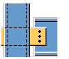
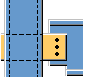
Shear tab position
| Option | Description |
|---|---|
|
|
Default Shear tab is on the near side. AutoDefaults can change this option. |
|
|
Shear tab is on the near side. |
|
|
Shear tab is on the far side. |
|
|
Shear tabs are on both sides. |
Shear tab rotation
| Option | Description |
|---|---|
|
|
Default Shear tab is not rotated. AutoDefaults can change this option. |
|
|
Shear tab is not rotated. |
|
|
Shear tab is rotated. |
Shear tab top and bottom edge
| Option | Description |
|---|---|
|
|
Default Shear tab is parallel to the first secondary part. AutoDefaults can change this option. |
|
|
Shear tab is parallel to the first secondary part. |
|
|
Shear tab is perpendicular to the main part. |
|
|
Shear tab is parallel to the second secondary part. |

Slot to column end
| Option | Description |
|---|---|
|
|
Default Slot is not created to the column end. AutoDefaults can change this option. |
|
|
Slot is not created to the column end. |
|
|
Slot is created to the column end. |


Dimensions
| Description | |
|---|---|
|
1 |
Bolt edge distance to the shear tab edge |
|
2 |
Shear tab corner radius |
Shear tab offset
| Description | |
|---|---|
|
1 |
Shear tab offset from the beam center line |
Secondary 1 bolts/Secondary 2 bolts tab
Use the Secondary 1 bolts and Secondary 2 bolts tabs to define the bolt group dimensions and bolt properties.
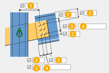
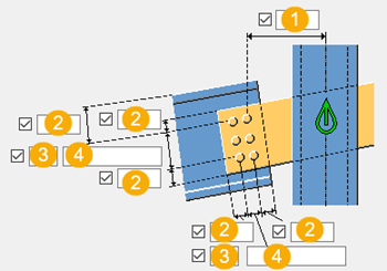
Bolt group dimensions
Define the dimensions for both the first secondary part and the second secondary part. You can also specify which bolts are deleted.
| Description | |
|---|---|
|
1 |
Dimension for horizontal bolt group position. |
|
2 |
Bolt edge distance. Edge distance is the distance from the center of a bolt to the edge of the part. |
|
3 |
Number of bolts. |
|
4 |
Bolt spacing. Use a space to separate bolt spacing values. Enter a value for each space between bolts. For example, if there are 3 bolts, enter 2 values. |
Bolt basic properties
|
Option |
Description |
Default |
|---|---|---|
|
Bolt size |
Bolt diameter. |
Available sizes are defined in the bolt assembly catalog. |
|
Bolt standard |
Bolt standard to be used inside the component. |
Available standards are defined in the bolt assembly catalog. |
|
Tolerance |
Gap between the bolt and the hole. |
|
|
Thread in mat |
Defines whether the thread may be within the bolted parts when bolts are used with a shaft. This has no effect when full-threaded bolts are used. |
Yes |
|
Site/Workshop |
Location where the bolts should be attached. |
Site |
Slotted holes
You can define slotted, oversized, or tapped holes.

|
Option |
Description |
Default |
|---|---|---|
|
1 |
Vertical dimension of slotted hole. |
0, which results in a round hole. |
|
2 |
Horizontal dimension of slotted hole, or allowance for oversized holes. |
0, which results in a round hole. |
|
Hole type |
Slotted creates slotted holes. Oversized creates oversized holes. No hole does not create holes. Tapped creates tapped holes. |
|
|
Rotate Slots |
When the hole type is Slotted, this option rotates the slotted holes. |
|
|
Slots in |
Part(s) in which slotted holes are created. The options depend on the component in question. |
Bolt assembly
The selected check boxes define which component objects (bolt, washers, and nuts) are used in the bolt assembly.
If you want to create a hole only, clear all the check boxes.

To modify the bolt assembly in an existing component, select the Effect in modify checkbox and click Modify.
Bolt length increase
Define how much the bolt length is increased. Use this option when, for example, painting requires the bolt length to be increased.

Secondary 1 notch/Secondary 2 notch tab
Use the Secondary 1 notch and Secondary 2 notch tabs to define the secondary part notch dimensions.
Shear tab top corner shape
| Option | Option | Description |
|---|---|---|
|
|
|
Default Square AutoDefaults can change this option. |
|
|
|
Automatic Square |
|
|
|
Square |
|
|
|
Bevel |
|
|
|
No notch |


Shear tab bottom corner shape
| Option | Option | Description |
|---|---|---|
|
|
|
Default Square AutoDefaults can change this option. |
|
|
|
Automatic Square |
|
|
|
Square |
|
|
|
Bevel |
|
|
|
No notch |


Shear tab cut
| Option | Option | Description |
|---|---|---|
|
|
|
Default Square AutoDefaults can change this option. |
|
|
|
Square |
|
|
|
Bevel |


Notch at the top
| Option | Option | Description |
|---|---|---|
|
|
|
Default Tekla Structures determines based on the connection geometry whether a notch is created. AutoDefaults can change this option. |
|
|
|
Automatic Tekla Structures determines based on the connection geometry whether a notch is created. |
|
|
|
No notch |
|
|
|
Notch is created, beam web is also cut. |
|
|
|
Notch is created, only the flange is cut. |


Notch at the bottom
| Option | Option | Description |
|---|---|---|
|
|
|
Default Tekla Structures determines based on the connection geometry whether a notch is created. AutoDefaults can change this option. |
|
|
|
Automatic Tekla Structures determines based on the connection geometry whether a notch is created. |
|
|
|
No notch |
|
|
|
Notch is created, beam web is also cut. |
|
|
|
Notch is created, only the flange is cut. |


Beam cut radius
| Description | |
|---|---|
|
1 |
Define the radius of the top and bottom beam cut. |
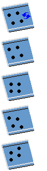
Staggering of bolts
| Option | Description |
|---|---|
|
|
Select how the bolts are staggered. |
Beam end fitting
| Option | Description |
|---|---|
|
|
Default Square AutoDefaults can change this option. |
|
|
Square |
|
|
Bevel |
|
|
Skewed |


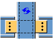
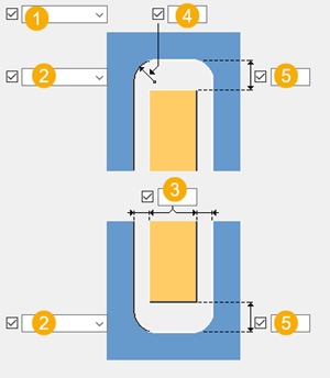
Prim slotting tab
Use the Prim slotting tab to define the main part cut for the shear tab.
Dimensions
| Description | |
|---|---|
|
1 |
Define the shear tab cut through the main part. |
|
2 |
Select the chamfer shape. |
|
3 |
Horizontal size of the cut created for the shear tab. |
|
4 |
Corner radius of the cut created for the shear tab. |
|
5 |
Vertical size of the cut created for the shear tab. Equal size is created at the top and bottom. |
Beam cut tab
Use the Beam cut tab to control weld backing bars, weld access holes, beam end preparations, and flange cuts.
Parts
| Option | Description |
|---|---|
|
Backing bar |
Thickness and width of the weld backing bar |
|
Option |
Description |
Default |
|---|---|---|
|
Pos_No |
Prefix and start number for the part position number. Some components have a second row of fields where you can enter the assembly position number. |
The default part start number is defined in the Components settings in . |
|
Material |
Material grade. |
The default material is defined in the Part material box in the Components settings in . |
|
Name |
Name that is shown in drawings and reports. |
|
|
Finish |
Describes how the part surface has been treated. |
Weld access hole dimensions

|
Description |
|
|---|---|
|
1 |
Gap between the secondary part top flange and the main part. |
|
2 |
Vertical dimensions for the top and the bottom weld access holes. |
|
3 |
Horizontal dimensions for the top and the bottom weld access holes. |
|
4 |
Gap between the secondary part web and the main part. Tekla Structures adds the value you enter here to the gap you enter on the Picture tab. |
|
5 |
Gap between the secondary part bottom flange and the main part. Tekla Structures adds the value you enter here to the gap you enter on the Picture tab. |
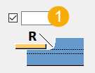
Weld access holes
|
Option |
Description |
Default |
|---|---|---|
|
|
Default Round weld access hole AutoDefaults can change this option. |
|
|
|
Round weld access hole |
|
|
|
Square weld access hole |
|
|
|
Diagonal weld access hole |
|
|
|
Round weld access hole with a radius that you can define in
|
|
|
|
Extended cone-shaped weld access hole with a radius and dimensions that you can define in
|
|
|
|
Cone-shaped weld access hole with radiuses that you can define in
Capital R defines the large radius (height). Small r defines the small radius. |
R = 35 r = 10 |

Beam end preparation
|
Option |
Description |
|---|---|
|
|
Default Top and bottom flange are prepared. AutoDefaults can change this option. |
|
|
Automatic Top and bottom flange are prepared. |
|
|
Beam end is not prepared. |
|
|
Top and bottom flange are prepared. |
|
|
Top flange is prepared. |
|
|
Bottom flange is prepared. |
Flange cut
|
Option for top flange |
Option for bottom flange |
Description |
|---|---|---|
|
|
|
Default Flange is not cut. AutoDefaults can change this option. |
|
|
|
Flange is not cut. |
|
|
|
Flange is cut. |
Weld backing bars
| Option | Description |
|---|---|
|
|
Default Backing bars are created inside the flanges. AutoDefaults can change this option. |
|
|
No backing bars are created. |
|
|
Backing bars are created inside the flanges. |
|
|
Backing bars are created outside the flanges. |


Weld backing bar length
Enter the length of the weld backing bar in the box below the options.
|
Option |
Description |
|---|---|
|
|
Default Absolute length of the backing bar AutoDefaults can change this option. |
|
|
Absolute length of the backing bar |
|
|
Extension beyond the edge of the flange |
Weld backing bar position
|
Option |
Description |
|---|---|
|
|
Enter a positive or a negative value to move the front end of the backing bar relative to the end of the flange. |

Assembly type
Define the location where the weld backing bar welds are made. When you select the Workshop option, Tekla Structures includes the backing bars in the assembly.
General tab
Click the link below to find out more:
Analysis tab
Click the link below to find out more:
Welds tab
Click the link below to find out more: