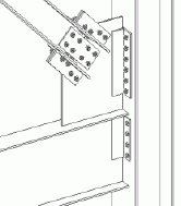
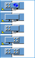
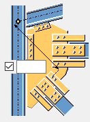
Wraparound gusset (58)
Wraparound gusset (58) connects 1 to 10 braces to the corner where two or three parts meet, usually two beams and a column, using a gusset plate. The gusset plate can be wrapped around the third part, usually a column. Bolts or welds the brace web to the gusset plate using connection plates, and bolts or welds the brace flange to the gusset plate using clip angles. Either connects the gusset plate directly to the two beams, or uses clip angles or shear tabs, or connection plates. The brace profile can be C or W.
Objects created
-
Gusset plate
-
Clip angles
-
Shear tabs
-
Connection plates
-
Shim plates
-
Bolts
-
Cuts
-
Welds
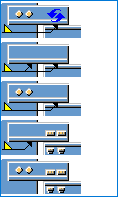
Use for
| Situation | Description |
|---|---|
|
|
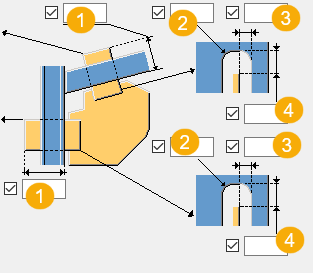
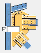
Brace profile: W Framing type: Beam and column Gusset plate is bolted to the column flange using a clip angle. Braces are bolted to the gusset plate using a connection plate and clip angles. |
Before you start
Create 2 or 3 parts that form a corner, and 1 to 10 braces.
Note:
Tekla Structures uses values in the joints.def file to create this component.
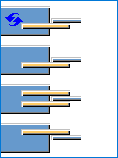
Selection order
-
Select the main part (the first part that forms the corner).
-
Select the secondary part (first brace).
-
Select the second secondary part (second brace).
-
Select the subsequent secondary parts (subsequent braces).
-
Select the secondary part that forms the corner.
-
If needed, select the column to wrap the gusset plate around the column where two beams and the column meet.
-
Click the middle mouse button to create the component.
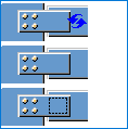
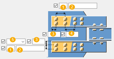
Part identification key
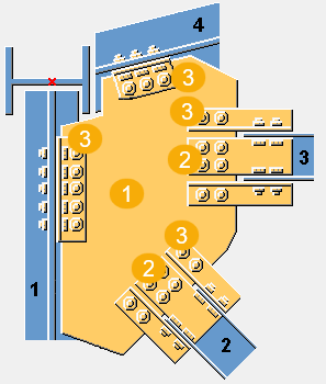
| Description | |
|---|---|
|
1 |
Gusset plate |
|
2 |
Connection plate |
|
3 |
Clip angle |
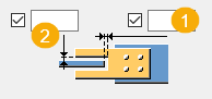
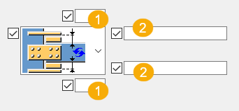
Picture tab
Use the Picture tab to define the shape of the gusset plate, location of the braces and clip angles, and the work point location.
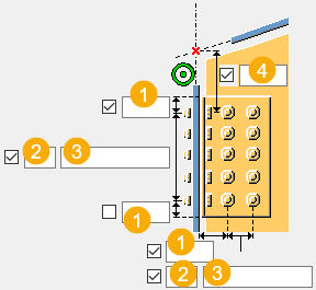
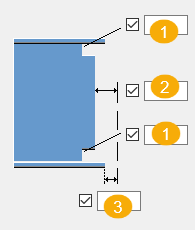
Dimensions
| Description | |
|---|---|
|
1 |
Define the gap distance between the gusset plate edge and the main part. |
|
2 |
Define the edge distance between the last secondary part and the last brace. |
|
3 |
Define the distance between the braces. |
|
4 |
Define the edge distance between the first brace and the main part. |
|
5 |
Define the gap distance between the gusset plate edge and the secondary part (second part that forms the corner). |
|
6 |
Define the gusset plate corner angle (in degrees). This value affects the gusset plate shape. |
|
7 |
Define the length of the edge of the gusset plate. This value affects the gusset plate shape. |
|
8 |
Define the gap distance between the gusset plate edge and the brace. |
|
9 |
Define the gusset plate edge distance in relation to the work point. |
|
10 |
Define the gusset plate edge distance to the flange of the third part. |
|
11 |
Define the clip angle edge distance in relation to the work point. |
|
12 |
Define the clip angle edge distance to the flange of the third part. |
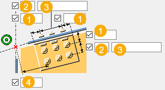
Work point position
| Option | Description |
|---|---|
|
|
Select the work point position. The default position is the point where the two main parts intersect. Tekla Structures uses the work point of a component to calculate check dimensions and part position dimensions in drawings. |
Gusset tab
Use the Gusset tab to define gusset plate, connection plate and clip angle properties.
Parts
| Option | Description |
|---|---|
|
Gusset |
Thickness, width and height of the gusset plate. |
|
Connection plates |
Thickness and height of the connection plates. |
|
Upper clip angle Lower clip angle |
Select the clip angle profile from the profile catalog. |
|
Option |
Description |
Default |
|---|---|---|
|
Pos_No |
Prefix and start number for the part position number. Some components have a second row of fields where you can enter the assembly position number. |
The default part start number is defined in the Components settings in . |
|
Material |
Material grade. |
The default material is defined in the Part material box in the Components settings in . |
|
Name |
Name that is shown in drawings and reports. |
|
|
Finish |
Describes how the part surface has been treated. |
Gusset plate connection
Define how the gusset plate is connected to the main part.
| Option | Description |
|---|---|
|
|
Default Gusset plate is connected to the main part with a clip angle. AutoDefaults can change this option. |
|
|
Gusset plate is connected to the main part with clip angles. Select to which side of the gusset plate the clip angles are created. |
|
|
Gusset plate is connected to the main part with a connection plate. Select to which side of the gusset plate the connection plate is created. |

Erection clearance
You can define the clearance for both the main part and the last secondary part connection plates or clip angles.
Gap dimensions
| Option | Description |
|---|---|
|
|
Define the gap dimension between the gusset plate and the connection plates or the clip angles. |
Connection plate cut through dimensions
| Description | |
|---|---|
|
1 |
Connection plate cut through length |
|
2 |
Chamfer radius |
|
3 |
Horizontal chamfer dimension |
|
4 |
Vertical chamfer dimension |
Clip angle orientation
Define how the clip angle is placed on the connection.
| Option | Description |
|---|---|
|
|
Default Clip angle is placed on the connection so that the longer leg is connected to the gusset plate. AutoDefaults can change this option. |
|
|
Clip angle is placed on the connection so that the longer leg is connected to the main part. |
Gusset plate shape
When you select the option to optimize the gusset plate weight, you can define whether the selection order of the braces affects the position of the braces.
| Option | Description |
|---|---|
|
|
Default AutoDefaults can change this option. |
|
|
This option optimizes the gusset plate weight. |


Gusset plate position on the brace
Define where to place the gusset plate on the brace. If needed, you can fine-tune the gusset plate position by moving the gusset plate in the z or in the y direction.
| Option | Description |
|---|---|
|
|
Default Gusset plate is positioned in the middle of the brace. AutoDefaults can change this option. |
|
|
Gusset plate is positioned on the top flange of the brace. |
|
|
Define how much the gusset plate is moved in the z direction. |
|
|
Define how much the gusset plate is moved in the y direction. |

Notch angle
| Option | Description |
|---|---|
|
|
Default Square notch If the gusset plate clashes with the column, the gusset plate is notched to wrap around the column. AutoDefaults can change this option. |
|
|
Square notch |
|
|
Bevel notch |


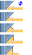
Notch chamfer type
| Option | Description |
|---|---|
|
|
Default Bevel chamfer AutoDefaults can change this option. |
|
|
No chamfer Notched edges are parallel to the edges of the gusset plate. |
|
|
Bevel chamfer |
|
|
Rounded chamfer calculated as a quarter of a circle. Enter the diameter of the circle as the horizontal dimension of the chamfer. |
|
|
Rounded chamfer calculated as a three quarters of a circle. Enter the diameter of the circle as the horizontal dimension of the chamfer. The center point of the circle is the corner of the notch. |
|
|
Corner of the gusset plate is beveled. |
|
|
Corner of the gusset plate is not notched or chamfered. |

Chamfer dimensions

| Description | |
|---|---|
|
1 |
Horizontal dimension of the chamfer |
|
2 |
Vertical dimension of the chamfer |
Gusset plate shape
The gusset plate edge can be perpendicular either to the main part or the secondary part.
| Option | Description |
|---|---|
|
|
Select the gusset plate edge shape between the last and second last secondary part. |
|
|
Select the gusset plate egde shape between the main part and the first secondary part. |

Brace conn tab
Use the Brace conn tab to control the properties of connection plates, clip angles, filler plates, and shear tabs, and the angle connection profile.
Plates
| Option | Description |
|---|---|
|
Connection plate |
Thickness and width of the connection plate. Select the connection plate profile. |
|
Upper clip angle Lower clip angle |
Select the clip angle profile. |
|
Filler plate |
Thickness, width and height of the filler plate. |
|
Upper shear tab |
Thickness, width and height of the upper shear tab. |
|
Lower shear tab |
Height of the lower shear tab. |
|
Option |
Description |
Default |
|---|---|---|
|
Pos_No |
Prefix and start number for the part position number. Some components have a second row of fields where you can enter the assembly position number. |
The default part start number is defined in the Components settings in . |
|
Material |
Material grade. |
The default material is defined in the Part material box in the Components settings in . |
|
Name |
Name that is shown in drawings and reports. |
|
|
Finish |
Describes how the part surface has been treated. |
Plate creation
| Option | Description |
|---|---|
|
|
Select whether one or two connection plates are created between the brace web and the gusset plate. |
|
|
Select whether a filler plate is created between the connection plate and the brace web. The default is that a filler plate is not created. |
|
|
Select the filler plate creation side. You can use this option when you have selected to create two connection plates. |
Clip angle creation
| Option | Description |
|---|---|
|
|
Define whether the braces are attached to the gusset plate using clip angles or shear tabs, and specify the number of clip angles to create. The default option is to create two clip angles below the brace web. |
Clip angle orientation
Define how the clip angle is placed on the connection.
| Option | Description |
|---|---|
|
|
Default Clip angle is placed on the connection so that the longer leg is connected to the gusset plate. AutoDefaults can change this option. |
|
|
Clip angle is placed on the connection so that the longer leg is connected to the main part. |
Connection type
| Option | Description |
|---|---|
|
|
Select the connection type (weld or bolts) between the gusset plate and the connection plate. |
|
|
When a filler plate is created, select whether to create a weld between the filler plate and the secondary part. You can use this setting when the connection type is bolts. |
|
|
Select the connection type (weld or bolt) between the gusset plate and the L profile. |

Connection plate gap dimensions
| Description | |
|---|---|
|
1 |
Horizontal gap dimension |
|
2 |
Vertical gap dimension |
Shim plates
Use the Shim plates tab tab to define shim plate properties.
Plates
| Option | Description |
|---|---|
|
Shim plate 1 Shim plate 2 Shim plate 3 |
Thickness, width and height of the shim plates. |
|
Option |
Description |
Default |
|---|---|---|
|
Pos_No |
Prefix and start number for the part position number. Some components have a second row of fields where you can enter the assembly position number. |
The default part start number is defined in the Components settings in . |
|
Material |
Material grade. |
The default material is defined in the Part material box in the Components settings in . |
|
Name |
Name that is shown in drawings and reports. |
|
|
Finish |
Describes how the part surface has been treated. |
Shim plate position
You can create shim plates when connecting braces to the gusset plate using clip angles.
| Description | |
|---|---|
|
1 |
Define the gap between the brace and connection plate. |
|
2 |
Define how many shim plates are created at the top and bottom flanges. Enter the shim plate profile numbers: 1, 2 or 3. These are the numbers that are on the upper part on the Shim plates tab. For example, if you want to create three shim plates at the top flange, and you want to use Shim plate 1 twice and Shim plate 1 once, enter 1 1 2. The first number you enter is the shim plate closest to the brace flange. |
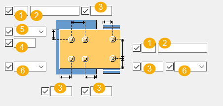
Gusset bolts 1 / Gusset conn 2 tab
Use the Gusset bolts 1 and Gusset conn 2 tabs to control the bolt group properties for bolts that connect the gusset plate to the main part and the secondary part, and to control the clip angle attachment.
Bolt group dimensions
|
1 |
Bolt edge distance. Edge distance is the distance from the center of a bolt to the edge of the part. |
|
2 |
Number of bolts. |
|
3 |
Bolt spacing. Use a space to separate bolt spacing values. Enter a value for each space between bolts. For example, if there are 3 bolts, enter 2 values. |
|
4 |
Vertical bolt group dimension in relation to the work point. Work point is the intersection point between the center lines of the main part and the last secondary part. |


| Description | |
|---|---|
|
1 |
Location where the bolts should be attached. |
|
2 |
Bolt edge distance. Edge distance is the distance from the center of a bolt to the edge of the part. |
|
3 |
Number of bolts. |
|
4 |
Bolt spacing. Use a space to separate bolt spacing values. Enter a value for each space between bolts. For example, if there are 3 bolts, enter 2 values. |
Bolt basic properties
|
Option |
Description |
Default |
|---|---|---|
|
Bolt size |
Bolt diameter. |
Available sizes are defined in the bolt assembly catalog. |
|
Bolt standard |
Bolt standard to be used inside the component. |
Available standards are defined in the bolt assembly catalog. |
|
Tolerance |
Gap between the bolt and the hole. |
|
|
Thread in mat |
Defines whether the thread may be within the bolted parts when bolts are used with a shaft. This has no effect when full-threaded bolts are used. |
Yes |
Slotted holes
You can define slotted, oversized, or tapped holes.

|
Option |
Description |
Default |
|---|---|---|
|
1 |
Vertical dimension of slotted hole. |
0, which results in a round hole. |
|
2 |
Horizontal dimension of slotted hole, or allowance for oversized holes. |
0, which results in a round hole. |
|
Hole type |
Slotted creates slotted holes. Oversized creates oversized holes. No hole does not create holes. Tapped creates tapped holes. |
|
|
Rotate Slots |
When the hole type is Slotted, this option rotates the slotted holes. |
|
|
Slots in |
Part(s) in which slotted holes are created. The options depend on the component in question. |
Bolt assembly
The selected check boxes define which component objects (bolt, washers, and nuts) are used in the bolt assembly.
If you want to create a hole only, clear all the check boxes.

To modify the bolt assembly in an existing component, select the Effect in modify checkbox and click Modify.
Bolt length increase
Define how much the bolt length is increased. Use this option when, for example, painting requires the bolt length to be increased.

Clip angle attachment type
Define how the clip angle is attached to the gusset plate and to the main part.
| Option | Description |
|---|---|
|
|
Default When the main part is a tube profile, the clip angles are welded to the main part and bolted to the secondary part. Otherwise the clip angles are bolted to both parts. AutoDefaults can change this option. |
|
|
Automatic When the main part is a tube profile, the clip angles are welded to the main part and bolted to the secondary part. Otherwise the clip angles are bolted to both parts. |
|
|
Main part is bolted and secondary part is welded. |
|
|
Main part is welded and secondary is part bolted. |
|
|
Both parts are bolted. |
|
|
Both parts are welded. |

Staggering of bolts
|
Option |
Description |
|---|---|
|
|
Default Not staggered AutoDefaults can change this option. |
|
|
Not staggered |
|
|
Staggered type 1 |
|
|
Staggered type 2 |
|
|
Staggered type 3 |
|
|
Staggered type 4 |
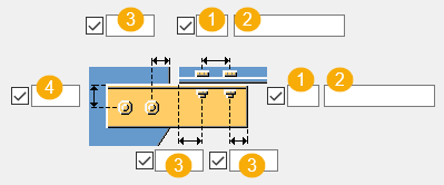
Brace bolts 1 / Brace bolts 2 tab
Use the Brace bolts 1 and Brace bolts 2 tabs to control the bolts that connect the braces to the gusset plate.
Bolt group dimensions
| Option | |
|---|---|
|
1 |
Number of bolts. |
|
2 |
Bolt spacing. Use a space to separate bolt spacing values. Enter a value for each space between bolts. For example, if there are 3 bolts, enter 2 values. |
|
3 |
Bolt edge distance. Edge distance is the distance from the center of a bolt to the edge of the part. |
|
4 |
Dimension for vertical bolt group position. |
|
5 |
Select how to measure the dimensions for vertical bolt group position.
|
|
6 |
Select the bolt type. |


Angle bolt group dimensions
| Option | |
|---|---|
|
1 |
Number of bolts. |
|
2 |
Bolt spacing. Use a space to separate bolt spacing values. Enter a value for each space between bolts. For example, if there are 3 bolts, enter 2 values. |
|
3 |
Bolt edge distance. Edge distance is the distance from the center of a bolt to the edge of the part. |
|
4 |
Dimension for vertical bolt group position. |
Bolt distance
Define the minimum distance from the connection plate bolts to the intersection point of the main part and brace center lines. If a brace is perpendicular to the main part, the distance is measured from the main part center line to the nearest bolts.
| Option | Option |
|---|---|
|
|
|
Vertical bolt position
| Option | Description |
|---|---|
|
|
Bolt position from the L profile edge. |
|
|
Bolt position from the secondary part center line. |


Bolt basic properties
|
Option |
Description |
Default |
|---|---|---|
|
Bolt size |
Bolt diameter. |
Available sizes are defined in the bolt assembly catalog. |
|
Bolt standard |
Bolt standard to be used inside the component. |
Available standards are defined in the bolt assembly catalog. |
|
Tolerance |
Gap between the bolt and the hole. |
|
|
Thread in mat |
Defines whether the thread may be within the bolted parts when bolts are used with a shaft. This has no effect when full-threaded bolts are used. |
Yes |
Slotted holes
You can define slotted, oversized, or tapped holes.
|
Option |
Description |
Default |
|---|---|---|
|
1 |
Vertical dimension of slotted hole. |
0, which results in a round hole. |
|
2 |
Horizontal dimension of slotted hole, or allowance for oversized holes. |
0, which results in a round hole. |
|
Hole type |
Slotted creates slotted holes. Oversized creates oversized holes. No hole does not create holes. Tapped creates tapped holes. |
|
|
Rotate Slots |
When the hole type is Slotted, this option rotates the slotted holes. |
|
|
Slots in |
Part(s) in which slotted holes are created. The options depend on the component in question. |
Bolt assembly
The selected check boxes define which component objects (bolt, washers, and nuts) are used in the bolt assembly.
If you want to create a hole only, clear all the check boxes.
To modify the bolt assembly in an existing component, select the Effect in modify checkbox and click Modify.
Bolt length increase
Define how much the bolt length is increased. Use this option when, for example, painting requires the bolt length to be increased.
Staggering of bolts
|
Option |
Description |
|---|---|
|
|
Default Not staggered AutoDefaults can change this option. |
|
|
Not staggered |
|
|
Staggered type 1 |
|
|
Staggered type 2 |
|
|
Staggered type 3 |
|
|
Staggered type 4 |
Clip angle extra bolts 1 tab
Use the Clip angle extra bolts 1 tab to define the clip angle bolt group dimensions and bolt properties.
Clip angle extensions
|
|
Select whether clip angles are extended, and the extension sides. |
Define the bolt group dimensions of the clip angle extensions.
| Description | |
|---|---|
|
1 |
Number of bolts. |
|
2 |
Bolt spacing. Use a space to separate bolt spacing values. Enter a value for each space between bolts. For example, if there are 3 bolts, enter 2 values. |
|
3 |
Bolt edge distance. Edge distance is the distance from the center of a bolt to the edge of the part. |
|
4 |
Bolt spacing to the bolts in the clip angle extension. |
|
5 |
Location where the bolts should be attached. |
Bolt basic properties
|
Option |
Description |
Default |
|---|---|---|
|
Bolt size |
Bolt diameter. |
Available sizes are defined in the bolt assembly catalog. |
|
Bolt standard |
Bolt standard to be used inside the component. |
Available standards are defined in the bolt assembly catalog. |
|
Tolerance |
Gap between the bolt and the hole. |
|
|
Thread in mat |
Defines whether the thread may be within the bolted parts when bolts are used with a shaft. This has no effect when full-threaded bolts are used. |
Yes |
Slotted holes
You can define slotted, oversized, or tapped holes.
|
Option |
Description |
Default |
|---|---|---|
|
1 |
Vertical dimension of slotted hole. |
0, which results in a round hole. |
|
2 |
Horizontal dimension of slotted hole, or allowance for oversized holes. |
0, which results in a round hole. |
|
Hole type |
Slotted creates slotted holes. Oversized creates oversized holes. No hole does not create holes. Tapped creates tapped holes. |
|
|
Rotate Slots |
When the hole type is Slotted, this option rotates the slotted holes. |
|
|
Slots in |
Part(s) in which slotted holes are created. The options depend on the component in question. |
Bolt assembly
The selected check boxes define which component objects (bolt, washers, and nuts) are used in the bolt assembly.
If you want to create a hole only, clear all the check boxes.
To modify the bolt assembly in an existing component, select the Effect in modify checkbox and click Modify.
Bolt length increase
Define how much the bolt length is increased. Use this option when, for example, painting requires the bolt length to be increased.
Beam cut tab
Use the Beam cut tab to control weld access holes, beam end preparations, and flange cuts.
Weld access hole dimensions
| Option | |
|---|---|
|
1 |
Dimension for the top and the bottom weld access holes. |
|
2 |
Gap between the secondary part web and the main part. |
|
3 |
Gap between the secondary part bottom flange and the main part. |
Weld access holes
| Option | Option | Description |
|---|---|---|
|
|
|
Default Round weld access hole AutoDefaults can change this option. |
|
|
|
Round weld access hole |
|
|
|
Square weld access hole |
|
|
|
Diagonal weld access hole |

Flange cut
|
Option for top flange |
Option for bottom flange |
Description |
|---|---|---|
|
|
|
Default Flange is not cut. AutoDefaults can change this option. |
|
|
|
Flange is not cut. |
|
|
|
Flange is cut. |
Beam end preparation
|
Option |
Description |
|---|---|
|
|
Default Top and bottom flange are prepared. AutoDefaults can change this option. |
|
|
Automatic Top and bottom flange are prepared. |
|
|
Beam end is not prepared. |
|
|
Top and bottom flange are prepared. |
|
|
Top flange is prepared. |
|
|
Bottom flange is prepared. |
General tab
Click the link below to find out more:
Design tab
Click the link below to find out more:
Analysis tab
Click the link below to find out more:
Welds
Click the link below to find out more: