New Edge release options for meshed walls
In the 2025 release, we have introduced new edge release options for meshed walls. These enable you to better model common construction conditions for masonry, cast-in-place, precast, timber, and CLT walls, such as expansion joints and pinned walls.
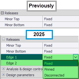
Previously, you could only apply releases to the top and bottom edges of each wall panel - now, you can also release the side edges.
While you can apply the new wall edge releases from a droplist in the Properties window (as shown above), or the Properties dialog, a further new enhancement allows you to also now apply wall releases graphically in a Review View.
When wall edges are released, coincident nodes may be created in order to correctly model the required connectivity - to help you to locate these a new Highlight coincident nodes command has been provided in the Solver View.
New Apply edge releases in the Properties window or Properties dialog
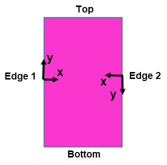
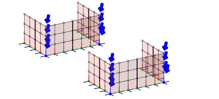
When using the Properties window/Properties dialog to apply edge releases, you will need to first identify which edge is Edge 1 and which is Edge 2 - you can do this from Scene Content by selecting Walls > Direction
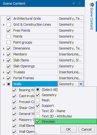
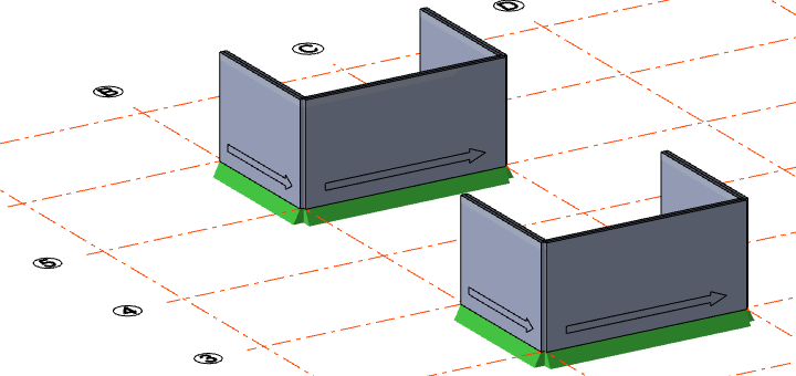
This displays an arrow on each wall starting at Edge 1 pointing to Edge 2.
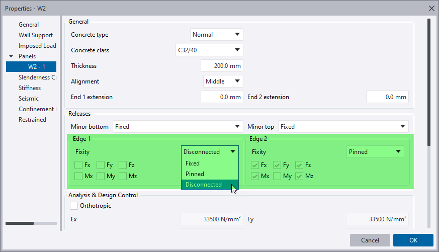
You can then set each edge to be "Fixed", "Pinned", or "Disconnected" as required from the Properties window or Properties dialog droplist.
If you set the releases in the Properties dialog you will see the different release options are also described in terms of the resulting degrees of freedom.
The sign convention for the degrees of freedom at the edges accords to the wall panel edge local coordinate system shown below.
New Apply wall releases graphically in a Review View
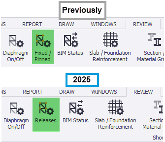
Rather than setting releases via the Properties dialog/Properties window, you will find it easier to activate a Review View and then use the Releases command to set them graphically.
(Previously, as shown below, this command was called "Fixed/Pinned" - it has been renamed "Releases" in the 2025 release as it now caters for wall fixity in addition to member fixity.)
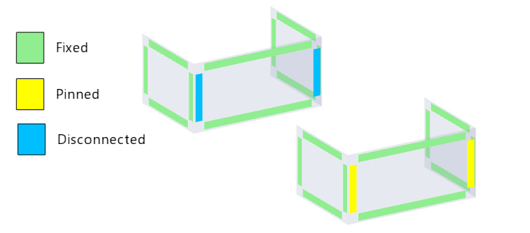
Using the graphical method allows you to see exactly how releases have been set throughout the model. You also don't need to know which is Edge 1 and Edge 2.
New Highlight coincident nodes in a Solver View
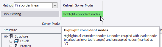
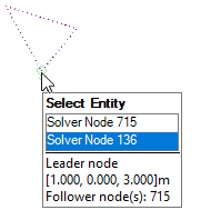
If a wall panel edge is "Pinned" or "Disconnected" and another wall panel or member connects to it, coincident nodes will be created. You can locate such nodes in a Solver View by selecting Highlight coincident nodes on the ribbon - this will place arrows adjacent to the coincident nodes.
The coincident nodes are categorised into two types:
-
Coupled coincident nodes - these are required where, for example, pinned panel edges meet fixed panel edges. Nodes along the edge are constrained to move together in a given direction. A "leader/follower” relationship is applied to the nodes to model the release condition. In the Solver View coupled coincident nodes have inverted triangles drawn above them.
-
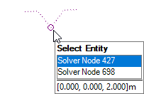
Uncoupled coincident nodes - these occur where, for example, disconnected panel edges meet fixed panel edges. As the nodes along the edge are not constrained to move together a "leader/follower" relationship is not required. In the Solver View uncoupled coincident nodes have a ‘V’ symbol drawn above them.
Viewing results and the effect of diaphragms
After analysis, you can view the effects of the release options that you’ve applied by opening a Results View to display 2D deflections.
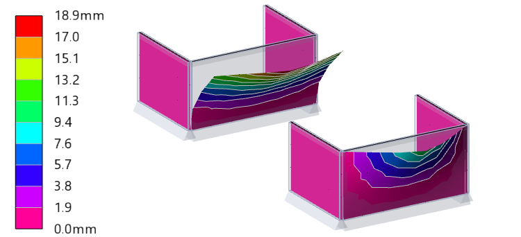
In the above example the wall with disconnected edges can move away from the perpendicular walls because there is no diaphragm constraining the top edges.
If a rigid or semi-rigid diaphragm had been modeled - all the walls attached to it would deflect by the same amount (or similar amount in the case of a semi-rigid diaphragm) in the plane of the diaphragm. For details, see: Disconnected walls attached to diaphragms or meshed slabs.