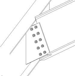
Shear plate simple (146)
Shear plate simple (146) connects a beam to a beam, or a beam to a column with a single square shear tab or double shear tabs. The shear tab is welded to the main part web and flanges, and bolted to the secondary beam web. The secondary beam can be leveled or sloped and/or skewed. A stiffener plate on the opposite side of the main beam web is optional.
Objects created
-
Shear tab (1 or 2)
-
Stiffener (optional)
-
Haunch plates (optional)
-
Weld backing bars (optional)
-
Seat angles
-
Welds
-
Bolts
-
Cuts
Use for
|
Situation |
Description |
|---|---|
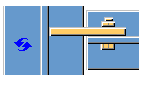
|
|
Simple shear tab connected to a beam. |
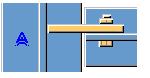
|
|
Simple shear tab connected to a beam. Some bolts have been deleted. |
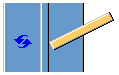
|
|
Simple shear tab connected to a beam. The secondary part is skewed. |
|
|
Simple shear tab connected to a beam. The secondary part is sloped and skewed. The bolts and shear tab are parallel with the secondary part. |
|
|
Simple shear tab connected to a beam with haunches and a stiffener plate. |
|
|
Simple shear tab connected to a beam. The secondary part is sloped and skewed. |
|
|
Simple shear tab connected to a column flange. |
|
|
Simple shear tab connected to a column flange/edge. |
|
|
Simple shear tab connected to a column flange with seat angle options. |
|
|
Simple shear tab connected to a column flange. Some bolts have been deleted. |


Selection order
-
Select the main part (column or beam).
-
Select the secondary part (beam).
The connection is created automatically when the secondary part is selected.
Note:
Tekla Structures uses values in the joints.def file to create this component.
Part identification key

|
Part |
|
|---|---|
|
1 |
Shear tab |
|
2 |
Haunch plate |
Picture tab
Use the Picture tab to control the beam end, flange, and web cuts.
Dimensions

| Description | Default | |
|---|---|---|
|
1 |
Size of the strip made to the secondary part flange. The cut of the flange is defined from the shear tab edge. |
The flange is automatically stripped when the shear tab crosses the flange. 20 mm |
|
2 |
The beam gap dimension adjusts the gap between the main part web and the secondary beam web. The dimension is measured either square to the main part or in the same direction as the secondary part. This option applies in square and skewed framing conditions. The dimension is only used when the Beam end cut option is set to default or automatic. |
20 mm Square to the main part |
Beam end cut
Define how the secondary beam end is cut. The beam is viewed from the side.
|
Option |
Description |
|---|---|
|
|
Default Bevel AutoDefaults can change this option. |
|
|
Automatic If the secondary beam is sloped less than 10 degrees, the beam end is cut square. Otherwise, the beam end is cut bevel. |
|
|
Square Cuts the end of the secondary beam square. |
|
|
Bevel Cuts the end of the secondary beam parallel to the edge of the main part. |
|
|
Square cut closer to the main part web Cuts the end of the secondary beam square and places the beam closer to the main part web. |
|
|
Clipped flange Cuts the corner of the flange at the end of the secondary beam. |
Beam web cut
Define how the secondary beam web end is cut. The beam is viewed from the top.
|
Option |
Description |
|---|---|
|
|
Default Bevel AutoDefaults can change this option. |
|
|
Bevel Cuts the end of the web bevel when the end of the secondary beam is cut bevel. |
|
|
Square Cuts the end of the web square even if the end of the secondary beam is cut bevel. |
Beam flange cut
Define how the secondary beam flange end is cut. The beam is viewed from the top.
|
Option |
Description |
|---|---|
|
|
Default Bevel AutoDefaults can change this option. |
|
|
Bevel Cuts the end of the flange bevel. |
|
|
Square Cuts a part of the flange square and leaves a part of it bevel. |
Beam bottom flange cut
|
Option |
Description |
|---|---|
|
|
Default Flange cut AutoDefaults can change this option. |
|
|
Notch The bottom of the secondary beam is notched if the shear tab crosses the flange. Enter the notch radius and height. |
|
|
Flange cut The secondary beam flange is cut on the same side as the shear tab if the shear tab crosses the flange. |
Plates tab
Use the Plates tab to control the size, position, number, orientation and shape of the shear tab.
Parts
| Option | Description |
|---|---|
| Tab plate | Shear tab plate thickness, width and height. |
| Plate washer | Plate washer thickness, width and height. |
|
Option |
Description |
Default |
|---|---|---|
|
Pos_No |
Prefix and start number for the part position number. Some components have a second row of fields where you can enter the assembly position number. |
The default part start number is defined in the Components settings in . |
|
Material |
Material grade. |
The default material is defined in the Part material box in the Components settings in . |
|
Name |
Name that is shown in drawings and reports. |
|
|
Finish |
Describes how the part surface has been treated. |
Shear tab position
Define the number and the side of shear tabs in single shear tab connections.
|
Option |
Description |
|---|---|
|
|
Default Far side shear tab AutoDefaults can change this option. |
|
|
Automatic The component automatically selects either the near side or the far side shear tab. The tab is created to the side of the secondary part when the angle between the main part and the secondary part is less than 90 degrees. |
|
|
Far side shear tab |
|
|
Near side and far side shear tab |
|
|
Near side shear tab |


Gap between shear tab and secondary part

|
1 |
Gap between the secondary part web and the shear tab. |
0 |
Shear tab position (sloped)
Define the position of shear tabs. The secondary part is sloped.
|
Option |
Description |
|---|---|
|
|
Default Shear tab edges reach the same level in the main part. AutoDefaults can change this option. |
|
|
Shear tab edges reach the same level in the main part. |
|
|
Shear tabs have the same length. |


Shear tab edge distance

|
Description |
|
|---|---|
|
1 |
Distance between the main part web and the edge of the shear tabs. |
Shear tab end cut
| Option | Description |
|---|---|
|
|
Default The shear tab end is not cut. AutoDefaults can change this option. |
|
|
Square The shear tab end is not cut. |
|
|
Bevel The shear tab end is cut parallel to the main part web. |


Shear tab chamfers

|
Description |
|
|---|---|
|
1 |
Horizontal dimension of the shear tab chamfer. |
|
2 |
Vertical dimension of the shear tab chamfer. |
Chamfer type
|
Option |
Description |
|---|---|
|
|
Default No chamfer AutoDefaults can change this option. |
|
|
No chamfer |
|
|
Line chamfer |
|
|
Convex arc chamfer |
|
|
Concave arc chamfer |


Shear tab orientation
|
Option |
Description |
|---|---|
|
|
Default Sloped AutoDefaults can change this option. |
|
|
Automatic The shear tab is sloped in the direction of the secondary beam. Both vertical edges of the shear tab are cut parallel to the end of the secondary beam. |
|
|
Sloped The shear tab is sloped in the direction of the secondary beam. Both vertical edges of the shear tab are cut parallel to the end of the secondary beam. |
|
|
Square |
|
|
Modified sloped Same as the Sloped option, but the vertical edge of the shear tab connected to the secondary beam is cut perpendicular to the secondary beam flange. |
Plate washer
Define plate washers for bolts and select the plate washer side.
| Option | Description |
|---|---|
|
|
Default No plate washer AutoDefaults can change this option. |
|
|
No plate washer |
|
|
One plate washer |
|
|
Individual square plate washers for each bolt |
|
|
Individual round plate washers for each bolt |


| Option | Description |
|---|---|

|
Select whether the plate washer is created for one shear tab or both shear tabs. |
Stiffeners tab
Use the Stiffeners tab to control the stiffener plate dimensions, orientation, position and type.
Opposite web stiffener plate dimensions
| Option |
Description |
|---|---|
|
Opposite web stiffener |
Opposite web stiffener plate thickness, width and height. |
|
Option |
Description |
Default |
|---|---|---|
|
Pos_No |
Prefix and start number for the part position number. Some components have a second row of fields where you can enter the assembly position number. |
The default part start number is defined in the Components settings in . |
|
Material |
Material grade. |
The default material is defined in the Part material box in the Components settings in . |
|
Name |
Name that is shown in drawings and reports. |
|
|
Finish |
Describes how the part surface has been treated. |
Stiffener creation
|
Option |
Description |
|---|---|
|
|
Default No stiffeners are created. AutoDefaults can change this option. |
|
|
Full Creates a full stiffener of the same height as the web of the main part. |
|
|
Determined by shear tab Tekla Structures determines the size of the stiffener based on the shear tab size. Tekla Structures attempts to keep the bottom edges of the stiffener plate and shear tab level, if possible. |
|
|
Partial Leaves a gap between the stiffener plate and the bottom flange of the main part. |
|
|
No stiffeners are created. |


Stiffener gap

| Description | |
|---|---|
|
1 |
Size of the gap between the main part flanges and the stiffener. |
|
2 |
Size of the gap between the main part web and the stiffener. |
Stiffener orientation
|
Option |
Description |
|---|---|
|
|
Default Stiffeners are parallel to the secondary part. AutoDefaults can change this option. |
|
|
Stiffeners are perpendicular to the main part. |
|
|
Stiffeners are parallel to the secondary part. |
Stiffener chamfers
|
Description |
|
|---|---|
|
1 |
Horizontal dimension of the chamfer. |
|
2 |
Vertical dimension of the chamfer. |
Chamfer type
|
Option |
Description |
|---|---|
|
|
Default Line chamfer AutoDefaults can change this option. |
|
|
No chamfer |
|
|
Line chamfer |
|
|
Convex arc chamfer |
|
|
Concave arc chamfer |


Haunch tab
Use the Haunch tab to control the haunch plate creation and chamfers in the secondary beam flanges.
Haunch plates
| Option |
Description |
|---|---|
|
Top plate |
Top haunch plate thickness, width and height. |
|
Bottom plate |
Bottom haunch plate thickness, width and height. |
|
Option |
Description |
Default |
|---|---|---|
|
Pos_No |
Prefix and start number for the part position number. Some components have a second row of fields where you can enter the assembly position number. |
The default part start number is defined in the Components settings in . |
|
Material |
Material grade. |
The default material is defined in the Part material box in the Components settings in . |
|
Name |
Name that is shown in drawings and reports. |
|
|
Finish |
Describes how the part surface has been treated. |
Haunch plate chamfers

|
Description |
|
|---|---|
|
1 |
Width of the top haunch plate chamfer. |
|
2 |
Height of the top haunch plate chamfer. |
|
3 |
Height of the bottom haunch plate chamfer. |
|
4 |
Width of the bottom haunch plate chamfer. |
Haunch plate creation
|
Option |
Description |
|---|---|
|
|
Default Top and bottom haunch plates are created, if needed. AutoDefaults can change this option. |
|
|
Automatic Top or bottom haunch plate or both are created, if needed. |
|
|
Top and bottom haunch plates are created. To create a single plate, enter 0 in the thickness (t) field for the plate you do not need (top or bottom plate). |
|
|
Haunch plates are not created. |


Notch tab
Use the Notch tab to automatically create notches for the secondary beam and to control the notch properties. The Notch tab has two sections: automatic properties (top section) and manual properties (bottom section). Automatic and manual notching properties work independently from each other.
Automatic notching
Automatic notching options affect both the top and the bottom flange.
Notch shape
Automatic notching is switched on when you select a notch shape.
| Option | Description |
|---|---|
|
Default Creates notches to the secondary beam. AutoDefaults can change this option. |
|
|
Creates notches to the secondary beam. The cuts are square to the main beam web. |
|
|
Creates notches to the secondary beam. The cuts are square to the secondary beam web. |
|
|
Creates notches to the secondary beam. The vertical cut is square to the main beam, and the horizontal cut is square to the secondary beam. |
|
|
Turns off automatic notching. |
|

|
Creates notches on both sides of the secondary beam. The cuts are square to the secondary beam. |
Notch size
| Option | Description |
|---|---|
|
|
Default The notch size is measured from the edge of the main beam flange and from underneath the top flange of the main beam. AutoDefaults can change this option. |
|
|
The notch size is measured from the edge of the main beam flange and from underneath the top flange of the main beam. |
|
|
The notch size is measured from the center line of the main beam and from the top flange of the main beam. |
|
|
The notch size is measured from the edge of the main beam flange and from the outer edge of the top flange of the main beam. |

Enter the horizontal and vertical values for the cuts.

Flange cut shape
|
Option |
Description |
|---|---|
|
|
Default Secondary beam flange is cut parallel to the main beam. AutoDefaults can change this option. |
|
|
Secondary beam flange is cut parallel to the main beam. |
|
|
Secondary beam flange is cut square. |
Notch dimension rounding
Use the notch dimension rounding options to define whether the notch dimensions are rounded up. Even if the dimension rounding is set to active, the dimensions are rounded up only when necessary.
|
Option |
Description |
|---|---|
|
|
Default Notch dimensions are not rounded. AutoDefaults can change this option. |
|
|
Notch dimensions are not rounded. |
|
|
Notch dimensions are rounded. Enter the horizontal and vertical rounding values. |
The dimensions are rounded up the nearest multiple of the value you enter. For example, if the actual dimension is 51 and you enter a round-up value of 10, the dimension is rounded up to 60.

Notch position
|
Option |
Description |
|---|---|
|
|
Default Creates the cut below the main beam flange. AutoDefaults can change this option. |
|
|
Creates the cut below the main beam flange. |
|
|
Creates the cut above the main beam flange. |
Notch chamfer
|
Option |
Description |
|---|---|
|
|
Default The notch is not chamfered. AutoDefaults can change this option. |
|
|
The notch is not chamfered. |
|
|
Creates the notch with a line chamfer. |
|
|
The notch is chamfered according to the radius you enter. |
Enter a radius for the chamfer.
![]()
Manual notching
Use manual notching when a part that does not belong to the connection clashes with the secondary beam. When you use manual notching, the connection creates cuts using the values you enter in the fields on the Notch tab. You can use different values for the top and the bottom flange.
Side of flange notch
The side of flange notch defines on which side of the beam the notches are created.
|
Option |
Description |
|---|---|
|
|
Default Creates notches on both sides of the flange. AutoDefaults can change this option. |
|
|
Automatic Creates notches on both sides of the flange. |
|
|
Creates notches on both sides of the flange. |
|
|
Creates notches on the near side of the flange. |
|
|
Creates notches on the far side of the flange. |
Flange notch shape
The flange notch shape defines the notch shape in the beam flange.
|
Option |
Description |
|---|---|
|
|
Default The entire flange of the secondary beam is cut as far back as you define. AutoDefaults can change this option. |
|
|
Automatic The entire flange of the secondary beam is cut as far back as you define. The default depth for the notch is twice the thickness of the secondary flange. The cut always runs the entire width of the secondary flange. |
|
|
Creates chamfers in the flange. If you do not enter a horizontal dimension, a chamfer of 45 degrees is created. |
|
|
Creates cuts to the flange with default values unless you enter values in the fields 1and 2. |
|
|
The flange is not cut. |
|
|
Creates cuts to the flange according to the value in the field 1 to make it flush with the web. |
|
|
Creates cuts to the flange according to the values in the fields 1 and 2. |
Flange notch depth
|
Option |
Description |
|---|---|
|
|
Default Flange notch depth. AutoDefaults can change this option. |
|
|
Flange notch depth. |
|
|
Flange notch depth with a dimension from the secondary beam web center line to the edge of the notch. |


Enter the value for flange notch depth.
![]()
Cut dimensions

|
Description |
Default |
|
|---|---|---|
|
1 |
Dimensions for the horizontal flange cuts. |
10 mm |
|
2 |
Dimensions for the vertical flange cuts. |
The gap between the notch edge and the beam flange is equal to the main part web rounding. The notch height is rounded up to the nearest 5 mm. |
Dimension from web to flange cut

|
Description |
|
|---|---|
|
1 |
Define the distance between the web and the flange cut. |
BCSA notch definition
Define whether the notch is created according to British Constructional Steelwork Association (BCSA) specifications.
|
Option |
Description |
|---|---|
|
Default |
Notch dimensions. |
|
Yes |
Creates a 50 mm notch for simple beam-to-beam connections. |
|
No |
Use the options on this Notch tab to define the notch dimensions. |
Cut clearance from the beam web
Define a tolerance value for the cut from the beam web. The value defines the portion of the web that is not cut.
Bolts tab
Use the Bolts tab to control the properties of the bolts that connect the shear tab to the secondary part.
Bolt group dimensions
Bolt group dimensions affect the size and shape of the shear tab.

| Description | |
|---|---|
| 1 |
Dimension for horizontal bolt group position. When the secondary beam is sloped or skewed, define whether the horizontal dimension is measured from the bolt group to the edge of the secondary part, or from the bolt group to the main part web.
The default is that the horizontal dimension is measured from the bolt group to the edge of the secondary part. Ensure that the
Beam end cut on the
Picture tab is set to square
|
| 2 |
Bolt edge distance. Edge distance is the distance from the center of a bolt to the edge of the part. |
| 3 |
Number of bolts. |
| 4 |
Bolt spacing. Use a space to separate bolt spacing values. Enter a value for each space between bolts. For example, if there are 3 bolts, enter 2 values. |
| 5 |
Dimension for vertical bolt group position. When the secondary beam is sloped, define whether the vertical dimension is measured from the bolt group to the edge of the secondary part, or from the bolt group to the edge of the main part.
The default is that the vertical dimension is measured from the bolt group the edge of the secondary part (sloped dimension). Ensure that the
Beam end cut on the
Picture tab is set to square
|
| 6 |
Select how to measure the dimensions for vertical bolt group position.
|
| 7 |
Define which bolts are deleted from the bolt group. Enter the bolt numbers of the bolts to be deleted and separate the numbers with a space. Bolt numbers run from left to right and from top to bottom. |


Staggering of bolts
|
Option |
Description |
|---|---|
|
|
Default Not staggered AutoDefaults can change this option. |
|
|
Not staggered |
|
|
Staggered type 1 |
|
|
Staggered type 2 |
|
|
Staggered type 3 |
|
|
Staggered type 4 |
Bolt group orientation
|
Option |
Description |
|---|---|
|
|
Default Square AutoDefaults can change this option. |
|
|
Automatic Square |
|
|
Staggered Bolts are staggered in the direction of the secondary part. |
|
|
Square Square bolt group is positioned horizontally. |
|
|
Sloped Square bolt group is sloped in the direction of the secondary part. |
Bolting direction
|
Option |
Description |
|---|---|
|
|
Default Bolting direction 1 AutoDefaults can change this option. |
|
|
Bolting direction 1 |
|
|
Bolting direction 2 |


Bolt basic properties
|
Option |
Description |
Default |
|---|---|---|
|
Bolt size |
Bolt diameter. |
Available sizes are defined in the bolt assembly catalog. |
|
Bolt standard |
Bolt standard to be used inside the component. |
Available standards are defined in the bolt assembly catalog. |
|
Tolerance |
Gap between the bolt and the hole. |
|
|
Thread in mat |
Defines whether the thread may be within the bolted parts when bolts are used with a shaft. This has no effect when full-threaded bolts are used. |
Yes |
|
Site/Workshop |
Location where the bolts should be attached. |
Site |
Cut length
Defines the depth at which Tekla Structures searches for the sections of the bolted parts. You can determine whether the bolt will go through one flange or two.
Slotted holes
You can define slotted, oversized, or tapped holes.

|
Option |
Description |
Default |
|---|---|---|
|
1 |
Vertical dimension of slotted hole. |
0, which results in a round hole. |
|
2 |
Horizontal dimension of slotted hole, or allowance for oversized holes. |
0, which results in a round hole. |
|
Hole type |
Slotted creates slotted holes. Oversized creates oversized holes. No hole does not create holes. Tapped creates tapped holes. |
|
|
Rotate Slots |
When the hole type is Slotted, this option rotates the slotted holes. |
|
|
Slots in |
Part(s) in which slotted holes are created. The options depend on the component in question. |
Bolt assembly
The selected check boxes define which component objects (bolt, washers, and nuts) are used in the bolt assembly.
If you want to create a hole only, clear all the check boxes.

To modify the bolt assembly in an existing component, select the Effect in modify checkbox and click Modify.
Bolt length increase
Define how much the bolt length is increased. Use this option when, for example, painting requires the bolt length to be increased.

Beam cut tab
Use the Beam cut tab to control weld backing bars, weld access holes, beam end preparations, and flange cuts.
Weld backing bar
| Option |
Description |
|---|---|
|
Weld backing bar |
Weld backing bar thickness and width. |
|
Option |
Description |
Default |
|---|---|---|
|
Pos_No |
Prefix and start number for the part position number. Some components have a second row of fields where you can enter the assembly position number. |
The default part start number is defined in the Components settings in . |
|
Material |
Material grade. |
The default material is defined in the Part material box in the Components settings in . |
|
Name |
Name that is shown in drawings and reports. |
|
|
Finish |
Describes how the part surface has been treated. |
Weld access hole dimensions

|
Description |
|
|---|---|
|
1 |
Gap between the secondary part top flange and the main part. |
|
2 |
Vertical dimensions for the top and the bottom weld access holes. |
|
3 |
Horizontal dimensions for the top and the bottom weld access holes. |
|
4 |
Gap between the secondary part web and the main part. Tekla Structures adds the value you enter here to the gap you enter on the Picture tab. |
|
5 |
Gap between the secondary part bottom flange and the main part. Tekla Structures adds the value you enter here to the gap you enter on the Picture tab. |
Weld access hole types
|
Option |
Description |
Default |
|---|---|---|
|
|
Default Round weld access hole AutoDefaults can change this option. |
|
|
|
Round weld access hole |
|
|
|
Square weld access hole |
|
|
|
Diagonal weld access hole |
|
|
|
Round weld access hole with a radius that you can define in
|
|
|
|
Extended cone-shaped weld access hole with a radius and dimensions that you can define in
|
|
|
|
Cone-shaped weld access hole with radiuses that you can define in
Capital R defines the large radius (height). Small r defines the small radius. |
R = 35 r = 10 |

Beam end preparation
|
Option |
Description |
|---|---|
|
|
Default Top and bottom flange are prepared. AutoDefaults can change this option. |
|
|
Automatic Top and bottom flange are prepared. |
|
|
Beam end is not prepared. |
|
|
Top and bottom flange are prepared. |
|
|
Top flange is prepared. |
|
|
Bottom flange is prepared. |
Flange cut
|
Option for top flange |
Option for bottom flange |
Description |
|---|---|---|
|
|
|
Default Flange is not cut. AutoDefaults can change this option. |
|
|
|
Flange is not cut. |
|
|
|
Flange is cut. |
Weld backing bar creation
|
Option for bottom backing bar |
Description |
|---|---|
|
|
Default Backing bars are created inside the flanges. AutoDefaults can change this option. |
|
|
No backing bars are created. |
|
|
Backing bars are created inside the flanges. |
|
|
Backing bars are created outside the flanges. |
Weld backing bar length
Enter the length of the weld backing bar in the box below the options.
|
Option |
Description |
|---|---|
|
|
Default Absolute length of the backing bar AutoDefaults can change this option. |
|
|
Absolute length of the backing bar |
|
|
Extension beyond the edge of the flange |
Weld backing bar position
|
Option |
Description |
|---|---|
|
|
Enter a positive or a negative value to move the front end of the backing bar relative to the end of the flange. |

Assembly type
Define the location where the weld backing bar welds are made. When you select the Workshop option, Tekla Structures includes the backing bars in the assembly.
Angle box tab
Use the Angle box tab to add a seat angle.
Seat angle
The purpose of seat angles is to carry loads from the secondary part. Seat angles can be positioned to top, bottom or both flanges of the secondary part. The seat angle can be stiffened, and bolted or welded to the main and secondary parts.
| Option |
Description |
|---|---|
|
Stiffeners |
Stiffener thickness, width and height. |
|
Profile |
Seat angle profile by selecting it from the profile catalog. |
|
Option |
Description |
Default |
|---|---|---|
|
Pos_No |
Prefix and start number for the part position number. Some components have a second row of fields where you can enter the assembly position number. |
The default part start number is defined in the Components settings in . |
|
Material |
Material grade. |
The default material is defined in the Part material box in the Components settings in . |
|
Name |
Name that is shown in drawings and reports. |
|
|
Finish |
Describes how the part surface has been treated. |
Seat angle position
|
Option |
Description |
|---|---|
|
|
Default No seat angle is created. AutoDefaults can change this option. |
|
|
No seat angle is created. |
|
|
Seat angle is created at the top of the flange. |
|
|
Seat angle is created at the bottom of the flange. |
|
|
Seat angles are created on both sides of the flange. |


Seat angle attachment
Seat angle is positioned at the top or at the bottom of the secondary part.
|
Option for top seat angle |
Option for bottom seat angle |
Description |
|---|---|---|
|
|
|
Default Bolted Seat angle is bolted to the main part and to the secondary part. AutoDefaults can change this option. |
|
|
|
Bolted Seat angle is bolted to the main part and to the secondary part. |
|
|
|
Welded-bolted Seat angle is welded to the main part and bolted to the secondary part. |
|
|
|
Bolted-welded Seat angle is bolted to the main part and welded to the secondary part. |
|
|
|
Welded Seat angle is welded to the main part and to the secondary part. |


Seat angle stiffener type
|
Option |
Description |
|---|---|
|
|
Default Rectangular stiffener plate AutoDefaults can change this option. |
|
|
Rectangular stiffener plate |
|
|
Triangular stiffener plate |
|
|
The line connecting the ends of the seat angle legs defines the stiffener plate shape. |


Stiffener offset dimension
Define the offset of bevel cuts for triangular stiffeners.

| Description | |
|---|---|
|
1 |
Horizontal offset dimension |
|
2 |
Vertical offset dimension |
Seat angle rotation
|
Option |
Description |
|---|---|
|
|
Default Seat angle is not rotated. AutoDefaults can change this option. |
|
|
Seat angle is not rotated. |
|
|
Seat angle is rotated horizontally 90 degrees. To stiffen the rotated seat angle, select the Middle stiffeners option in the Middle stiffener position list. |

Seat angle orientation
|
Option |
Description |
|---|---|
|
|
Default The longer leg of the seat angle is connected to the secondary part. AutoDefaults can change this option. |
|
|
The longer leg of the seat angle is connected to the secondary part. |
|
|
The longer leg of the seat angle is connected to the main part. |
|
|
Automatic The longer leg of the seat angle is connected to the part where bolts reach furthest from the seat angle corner. |


Seat angle side stiffener position
|
Option |
Description |
|---|---|
|
|
Default No side stiffeners are created. AutoDefaults can change this option. |
|
|
No side stiffeners are created. |
|
|
Near side stiffeners are created. |
|
|
Far side stiffeners are created. |
|
|
Near side and far side stiffeners are created. |
Seat angle middle stiffener position
|
Option |
Description |
|---|---|
|
|
Default According to bolts AutoDefaults can change this option. |
|
|
No middle stiffener plate is created. |
|
|
Middle stiffeners The stiffener plate is positioned in the middle of the seat angle. Enter the number of middle stiffeners in the Number of middle stiffeners box. Multiple stiffeners are centered and equally spaced. |
|
|
According to bolts The stiffener plate is positioned between the bolts in the middle of the bolt spacing. By default, stiffener is created between every two bolts. Enter the number of middle stiffeners in the box below the According to bolts option. |


Seat angle offset

|
Description |
|
|---|---|
|
1 |
Seat angle horizontal offset from the center line of the main part. |
Seat angle gap

|
Description |
|
|---|---|
|
1 |
Top gap and bottom gap between the seat angle and the secondary part. |
Seat angle chamfers

|
Description |
|
|---|---|
|
1 |
Vertical dimension of the chamfer. |
|
2 |
Horizontal dimension of the chamfer. |
Chamfer type
|
Option |
Description |
|---|---|
|
|
Default No chamfer AutoDefaults can change this option. |
|
|
No chamfer |
|
|
Line chamfer |
|
|
Convex arc chamfer |
|
|
Concave arc chamfer |


BoxPBolts tab
Use the BoxPBolts tab to control properties of the bolts that connect the seat angle to the main part.
Seat angle bolt group dimensions

|
Description |
|
|---|---|
|
1 |
Dimension for horizontal bolt group position. The dimension is defined from the middle line of the secondary beam. |
|
2 |
Edge distance is the distance from the center of a bolt to the edge of the part. Bolt edge distance. |
|
3 |
Number of bolts. |
|
4 |
Bolt spacing. Use a space to separate bolt spacing values. Enter a value for each space between bolts. For example, if there are 3 bolts, enter 2 values. |
|
5 |
Dimension for vertical bolt group position. The dimension is defined from the bottom of the secondary beam. |
Bolt basic properties
|
Option |
Description |
Default |
|---|---|---|
|
Bolt size |
Bolt diameter. |
Available sizes are defined in the bolt assembly catalog. |
|
Bolt standard |
Bolt standard to be used inside the component. |
Available standards are defined in the bolt assembly catalog. |
|
Tolerance |
Gap between the bolt and the hole. |
|
|
Thread in mat |
Defines whether the thread may be within the bolted parts when bolts are used with a shaft. This has no effect when full-threaded bolts are used. |
Yes |
|
Site/Workshop |
Location where the bolts should be attached. |
Site |
- Top refers to the bolt group that connects the top seat angle to the main part.
- Bottom refers to the bolt group that connects the bottom seat angle to the main part.
Slotted holes
You can define slotted, oversized, or tapped holes.
|
Option |
Description |
Default |
|---|---|---|
|
1 |
Vertical dimension of slotted hole. |
0, which results in a round hole. |
|
2 |
Horizontal dimension of slotted hole, or allowance for oversized holes. |
0, which results in a round hole. |
|
Hole type |
Slotted creates slotted holes. Oversized creates oversized holes. No hole does not create holes. Tapped creates tapped holes. |
|
|
Rotate Slots |
When the hole type is Slotted, this option rotates the slotted holes. |
|
|
Slots in |
Part(s) in which slotted holes are created. The options depend on the component in question. |
Bolt length increase
Define how much the bolt length is increased. Use this option when, for example, painting requires the bolt length to be increased.
BoxSBolts tab
Use the BoxSBolts tab to control the properties of the bolts that connect the seat angle to the secondary part.
Seat angle bolt group dimensions

|
Description |
|
|---|---|
|
1 |
Dimension for vertical bolt group position. The dimension is defined from the middle line of the secondary beam. |
|
2 |
Bolt edge distance. Edge distance is the distance from the center of a bolt to the edge of the part. |
|
3 |
Number of bolts. |
|
4 |
Bolt spacing. Use a space to separate bolt spacing values. Enter a value for each space between bolts. For example, if there are 3 bolts, enter 2 values. |
|
5 |
Dimension for horizontal bolt group position. The dimension is defined from the bottom of the secondary beam. |
Bolt basic properties
|
Option |
Description |
Default |
|---|---|---|
|
Bolt size |
Bolt diameter. |
Available sizes are defined in the bolt assembly catalog. |
|
Bolt standard |
Bolt standard to be used inside the component. |
Available standards are defined in the bolt assembly catalog. |
|
Tolerance |
Gap between the bolt and the hole. |
|
|
Thread in mat |
Defines whether the thread may be within the bolted parts when bolts are used with a shaft. This has no effect when full-threaded bolts are used. |
Yes |
|
Site/Workshop |
Location where the bolts should be attached. |
Site |
- Top refers to the bolt group that connects the top seat angle to the secondary part.
- Bottom refers to the bolt group that connects the bottom seat angle to the secondary part.
Slotted holes
You can define slotted, oversized, or tapped holes.
|
Option |
Description |
Default |
|---|---|---|
|
1 |
Vertical dimension of slotted hole. |
0, which results in a round hole. |
|
2 |
Horizontal dimension of slotted hole, or allowance for oversized holes. |
0, which results in a round hole. |
|
Hole type |
Slotted creates slotted holes. Oversized creates oversized holes. No hole does not create holes. Tapped creates tapped holes. |
|
|
Rotate Slots |
When the hole type is Slotted, this option rotates the slotted holes. |
|
|
Slots in |
Part(s) in which slotted holes are created. The options depend on the component in question. |
Bolt length increase
Define how much the bolt length is increased. Use this option when, for example, painting requires the bolt length to be increased.
General tab
Click the link below to find out more:
Design type tab
Click the link below to find out more:
Analysis tab
Click the link below to find out more:
Welds
Click the link below to find out more: