Reinforcement settings for drawings (rebar_config.inp)
Tekla Structures uses the settings in the rebar_config.inp file in the system folder (XS_SYSTEM), firm folder, or in the project folder to define the following reinforcement-related settings in drawings:
-
Selected area-specific reinforcing bar bending schedule
-
Rounding of bar dimensions
-
Available symbols for meshes, strands, and unbonding
-
Appearance of reinforcement pull-outs
To modify the settings, open rebar_config.inp in a standard text editor.
The entries in the rebar_config.inp are listed and described below:
|
Entry |
Description |
|---|---|
|
|
No longer used. Define these properties in the drawing properties. |
|
|
|
|
|
|
|
|
|
|
|
= Affects the separator in reinforcement marks. |
|
|
= Separator between different exact spacing values in reinforcement marks. |
|
|
= Separator between the number of bars and their exact spacing values in reinforcement marks. |
|
|
Set a tolerance value for the angle. Angles that differ from the set tolerance value less than the tolerance are recognized and lead to a correct bending shape. Enter the tolerance value in radians, not in degrees. The default value is 0.01 radians, which is 0.573 degrees. This applies to all bending shapes. |
|
|
Set a tolerance value. Depending on the value, slightly curved reinforcing bars get a straight shape. If reinforcing bar diameter is 20 mm and radius is 200 m then value 20/200000 = 0.0001. This variable defines the correct curved reinforcing bar in case of long reinforcing bars to get a correct shape for the bar. This option is used in comparing the relation of the reinforcing bar diameter and radius. If the relation is smaller than
|
|
|
Set to 1 to show the pullout bending radii using a multiplier instead of mm.
|
PullOutBendingRadiusDimensionUnit |
Define the unit to be used in the bending radius text in the pull-out. The options are: 0 = auto: This option defaults to mm in the metric environment and foot and inch in the imperial environment. 1 = mm 2 = cm 3 = m 4 = inch 5 = foot and inch 6 = cm or m If If PullOutDimensionFormat and PullOutDimensionPrecision. |
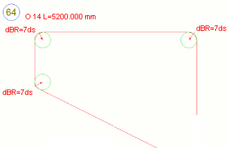
PullOutBendingRadiusPrefix |
Define the prefix to be used in the bending radius
text in the pull-out. If PullOutBendingRadiusPrefix is not set, it will be
defaulted to dBR=. If it is set to
be empty, no prefix is used. |
|
|
No longer in use. |
|
|
No longer in use. |
|
|
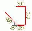
Defines which bending schedule is used. Affects bending shapes in templates and reports. The available schedules are FIN, SWE, UK, US. When you number the model, the bending shape for the bar is given according to this information. For example, in the Default environment, the bending shapes are letters A, B, C, and so on. |
|
|
Options:
|
|
|
Sets the rounding accuracy for bar dimensions. The default is 1 mm. Tekla Structures rounds individual bar dimensions up or down according to the option you select for
|
|
|
Sets the rounding accuracy for the total bar length. The default is 10 mm. Tekla Structures rounds individual bar dimensions up or down according to the option you select for
|
|
|
Points to the symbol file that contains the available reinforcing bar bent symbols. By default, points to the file bent.sym, which in the default environment is located in the folder ..\ProgramData\Trimble\Tekla Structures\<version>\environments\common\symbols. |
|
|
Points to the mesh symbol file that contains the available mesh symbols. Affects the available reinforcement mesh symbols in drawings. By default, points to the mesh.sym file in the ...\Tekla Structures\<version>\environments\common\symbols folder. |
|
|
Points to the strand symbol file that contains the available strand symbols. Affects drawings. By default, points to the strand.sym file in the ...\Tekla Structures\<version>\environments\common\symbols folder. |
|
|
Points to the unbonding symbol file that contains the available unbonding symbols. |
|
|
Template for rebar mesh size = |
|
|
Defines the format for displaying the dimensions. The format follows the dimension properties format. Options:
|
|
|
Sets the level of precision. The precision is calculated using the following formula: 1/value = precision.
In metric systems, you may want to use the values 1, 10, and 100, and in imperial systems, the values 2, 4, 8, 16 and 32, for example. |
|
|
Defines the units to use. Options:
|
|
|
Sets the color for the pull-outs in reinforcement marks. Options:
|
|
|
Sets the line type for reinforcing bar shape in pull-outs. Options:
|
|
|
Sets the representation type. Options:
|
|
|
Sets the color for the angle in pull-outs. Options:
|
|
|
Sets the line type for angle lines in pull-outs. Options:
|
|
|
Sets a minimum length for the small leader lines that point to the dimension text. The default value is 10 mm. To switch leader lines off completely, use a large value. |
|
|
Defines whether duplicate dimensions are shown multiple times for one bar. Options:
|
|
|
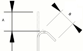
Defines if the US/NA style of dimension will be shown for hooks over 90 degrees. Options:
See the image below for the difference between the US/NA (A) and European (B) hook dimension. |