Tower generation (S43)
Tower generation (S43) creates a complete tower, with a square or rectangular base.
Objects created
-
Tower legs (4 L profiles)
-
Bracing panels (L, flat, U, twin profiles)
Use for
| Situation | Description |
|---|---|
|
|
Complete tower with a rectangular base |
Before you start
Check the current work plane, as it affects the position of the tower.
Tekla Structures creates the tower along the z axis of the current work plane. If the tower has a rectangular base, the longest side of the base runs parallel to the x axis.
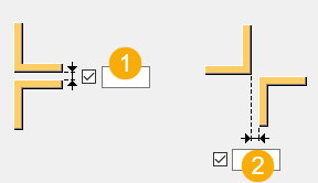
| Description | |
|---|---|
|
1 |
Tower base |
|
2 |
Tower top |
Selection order
-
Pick a point to indicate the position of the tower leg at the bottom left corner of the tower base.
The tower is created automatically when you pick the point.
Part identification key
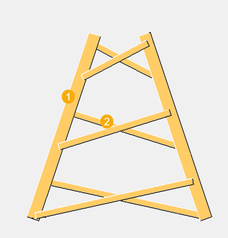
| Description | |
|---|---|
|
1 |
Tower leg |
|
2 |
Bracing panels |
Picture tab
Use the Picture tab to define the number of bracing panels, and the dimensions that control the location of cross braces on the tower legs.
Bracing panels
| Option | Description |
|---|---|
|
Number of diagonals |
Define how many bracing panels are created between each pair of tower legs. |
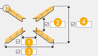
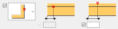
Dimensions
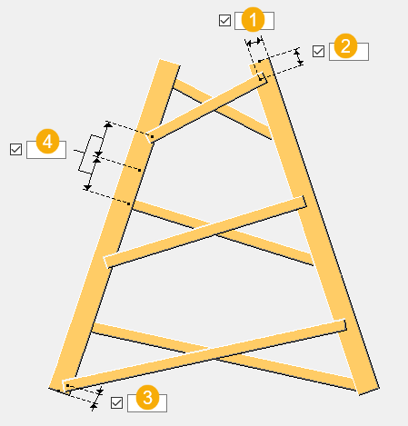
| Description | |
|---|---|
|
1 |
Bracing panel distance from the tower leg outer edge |
|
2 |
Bracing panel edge distance from the tower leg top |
|
3 |
Bracing panel edge distance from the tower leg bottom |
|
4 |
Distance between the bracing panels |
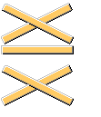
Bracing panel layout
You can select the layout type for the bracing panels on the Tower parameters tab. The default layout is cross bracing:
![]()
Parts tab
Use the Parts tab to define the part properties, and the profiles for legs and bracing.
Parts
| Option | Description |
|---|---|
|
Profile 1, Profile 2, Profile 3, Profile 4, Profile 5, Profile 6, Profile 7, Profile 8 |
Select the profile from the profile catalog. |
|
Diagonal profiles |
Select the profile from the profile catalog. |
|
Horizontal profiles |
Select the profile from the profile catalog. |
|
Option |
Description |
Default |
|---|---|---|
|
Pos_No |
Prefix and start number for the part position number. Some components have a second row of fields where you can enter the assembly position number. |
The default part start number is defined in the Components settings in . |
|
Material |
Material grade. |
The default material is defined in the Part material box in the Components settings in . |
|
Name |
Name that is shown in drawings and reports. |
Leg parameters tab
Use the Leg parameters tab to define angle profile creation and dimensions, lift length, and to tile profiles.
Profiles
| Option | Description |
|---|---|
|
Profiles for parts |
Define the profiles used for the tower legs. For example, enter 6*1 to create tower legs each made up of 6 lifts using the profile type you defined for profile 1. |
|
Finish |
Define how the part surface is treated. |
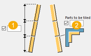
Lift length and parts to tile
| Description | |
|---|---|
|
1 |
Define the number and length of the lifts that make up each leg. For example, enter 6*6000 to create tower legs using 6 lifts, each 6000 long. |
|
2 |
To tile specific leg lifts, enter the numbers of the lifts to tile, counting from the bottom of the leg. For example, enter 3 5 to tile lifts 3 and 5. |
Cutback distance
| Description | |
|---|---|
|
1 |
Define the cutback distance at the top and the bottom to splice the tower legs. |
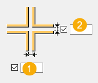
Distance between angle profiles
| Description | |
|---|---|
|
1 |
Distance in the x direction |
|
2 |
Distance in the y direction |
Angle profile creation
| Option | Description |
|---|---|
|
|
Define how many angle profiles form each leg, in a cross section. The default option is one angle profile. |
Create sloping legs
Define the x and y dimensions of the base and the top of the tower to create sloping legs.
| Description | |
|---|---|
|
1 |
Top x direction |
|
2 |
Top y direction |
|
3 |
Base x direction |
|
4 |
Base y direction |
Tower parameters tab
Use the Tower parameters tab to define the bracing type and class for the bracing.
Angle leg orientation
| Option | Description |
|---|---|
|
|
Select the angle leg orientation. |

Bracing panel layout
| Option | Description |
|---|---|
|
|
Select the bracing panel layout. The default layout is cross bracing, the second option. |
Angle profile rotation
| Option | Description |
|---|---|
|
|
Select the angle profile rotation. |
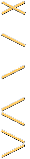
Diagonal bracing layout
| Option | Direction |
|---|---|
|
|
Select the layout for diagonal bracing. You can define the number of bracing panels on the Picture tab. |
Cross distance and class
| Option | Description |
|---|---|
|
Method to find cross distances |
Select whether diagonal bracing panels are created by equal or different cross distances, or by Z levels. |
|
Z Levels |
Define the Z levels for the diagonal bracing panels. |
|
Class number of horizontal profiles Class number of right diagonal profiles Class number of left diagonal profiles |
Define the class of the profiles. |
Twin profiles tab
Use the Twin profiles tab to define whether twin profiles are used.
Twin profile creation
| Option | Description |
|---|---|
|
|
Select whether to create a twin profile. |

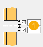
Twin profile dimensions
| Description | |
|---|---|
|
1 |
Vertical distance between the profiles |
|
2 |
Horizontal distance between the profiles |
Twin profile rotation
| Option | Description |
|---|---|
|
|
Select the position and rotation for the twin profiles. |

Model points tab
Use the Model points tab to define construction points on tower legs and braces for attaching the component to parts.
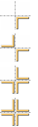
Construction points
Construction points are points that you can pick to attach components to parts. For example, you might create construction points on tower legs for connecting bracing to the legs.
-
Select the location of points. You can select that no points are created, points are created on the outer or inner face of a brace, or on both faces.
-
Enter the distance between the points and the quantity of points. For example, enter 400*4 to create 4 points, 400 mm apart.
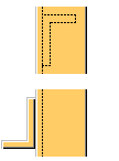
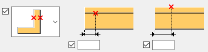
The example images below show the options of the horizontal brace.
| Option | Description |
|---|---|
|
|
No points |
|
|
Inner face of the brace |
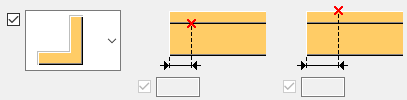
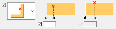
|
|
Outer face of the brace |
 |
Both faces of the brace |
Joints tab
Use the Joints tab to define the components that connect the braces to the tower legs.
You can use different components to connect the left and right diagonal braces, and the horizontal braces.
You cannot use custom components to connect the braces to the tower legs.
-
Select a component from the list.
If you want to use a component that is not on the list, select Custom and enter the component number.
-
Enter the name of the predefined set of properties for the component.