Tapered column 2 (S44)
Tapered column 2 (S44) creates a welded built-up column, which can be tapered or straight. You can control the taper and the size of the spliced material.
Objects created
-
Web plates
-
Top flange plates
-
Bottom flange plates
-
Welds
Use for
| Situation | Description |
|---|---|
|
|
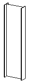
A simple straight column built up from two flange plates and a web plate. |
|
|
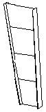
A more complex tapered column, with several plates forming the web, and top and bottom flanges. |
Before you start
Ensure that you have a point to pick.
Selection order
-
Pick the position of the column.
The column is created automatically when you pick the position.
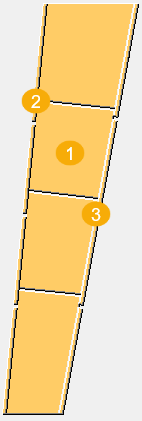
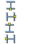
Part identification key
| Description | |
|---|---|
|
1 |
Web plate |
|
2 |
Top flange plate |
|
3 |
Bottom flange plate |
Picture tab
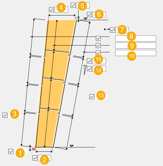
Use the Picture tab to define the column dimensions and location relative to the picked points.
Dimensions
| Description | |
|---|---|
|
1 |
Distance from the first point picked to the end of the column. |
|
2 |
Column width at the first end. |
|
3 |
Gap between the top flange plates. |
|
4 |
Column width at the second end. |
|
5 |
Distance from the last point picked to the end of the column. |
|
6 |
Column height. |
|
7 |
Column end alignment dimension. |
|
8 |
Length of the top flange plates. For example, to have four one-meter sections, enter 4*1000. If you want to create the flange or web from a single plate, leave the box empty. |
|
9 |
Length of the web plates. For example, to have four one-meter sections, enter 4*1000. If you want to create the flange or web from a single plate, leave the box empty. |
|
10 |
Length of the bottom flange plates. For example, to have four one-meter sections, enter 4*1000. If you want to create the flange or web from a single plate, leave the box empty. |
|
11 |
Gap between the bottom flange plates. |
|
12 |
Horizontal sloping of the beam, as a percentage. |
|
13 |
Column rotation dimension. |
Column rotation
| Option | Description |
|---|---|
|
|
Select how the column is rotated and define the dimension for the rotation. |
Column position to picked point
| Option | Description |
|---|---|
|
|
Moves the column so that the point is located at the column flange. |
|
|
Moves the column so that the point is located at the column web. |
|
|
Moves the column so that the point is located in the middle of the column cross section. |
|
|
Moves the column so that the point is located at the column web. |
|
|
Moves the column so that the point is located at the column flange. |


Web plate orientation
| Option | Description |
|---|---|
|
|
Web plates are cut perpendicular to the top flange. |
|
|
Web plates are cut vertically. |


Column end alignment
| Option | Description |
|---|---|
|
|
Cut is vertical or horizontal. |
|
|
Cut is perpendicular to the top flange. |
|
|
Cut is relative to the current position of the work plane. |


Depth measure
| Option | Description |
|---|---|
|
|
Depth is calculated from the outer surfaces of the top and bottom flanges. |
|
|
Depth is the depth of the web. |


Column flange
| Option | Description |
|---|---|
|
|
Column flange is perpendicularly fitted to the web. |
|
|
Column flange is aligned with the web. |


Parts tab
Use the Parts tab to define the plate properties.
Parts
| Option | Description |
|---|---|
|
Top fl. profile |
Select the profile from the profile catalog. |
|
Bottom fl. profile |
Select the profile from the profile catalog. |
|
Web pl. thickness |
Thickness of the web plate. |
|
Option |
Description |
Default |
|---|---|---|
|
Pos_No |
Prefix and start number for the part position number. Some components have a second row of fields where you can enter the assembly position number. |
The default part start number is defined in the Components settings in . |
|
Material |
Material grade. |
The default material is defined in the Part material box in the Components settings in . |
|
Name |
Name that is shown in drawings and reports. |
|
|
Finish |
Describes how the part surface has been treated. |
Welds
Click the link below to find out more: