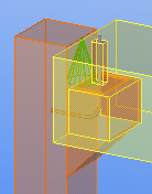
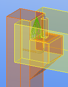
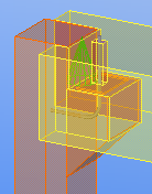
Corbel connection (14)
Corbel connection (14) connects a beam to a column using a straight, beveled, or rounded corbel and reinforcing bars or fastening plates.
Objects created
-
Corbel
-
Bearing plate
-
Drainage holes in bearing plate (1 or 2) (optional)
-
Reinforcing bars (1 or 2) (optional)
-
Bolt plates for reinforcing bars
-
Nuts for reinforcing bars
-
Recesses for bolt plates and nuts
-
-
Fastening plates (2) (optional)
-
Recesses for fastening plates
-
Use for
| Situation | Description |
|---|---|
|
|
Connects a beam to a column using a reinforcing bar and a beveled corbel. |
|
|
Connects a beam to a column using fastening plates and a rounded corbel. |
Selection order
-
Select the main part (column).
-
Select the secondary part (beam).
The connection is created automatically when the secondary part is selected.
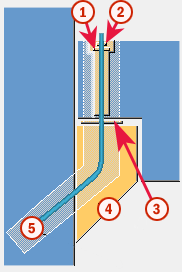
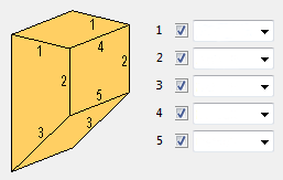
Part identification key
| Part | |
|---|---|
|
1 |
Bolt plate |
|
2 |
Nut |
|
3 |
Bearing plate |
|
4 |
Corbel |
|
5 |
Reinforcing bar |
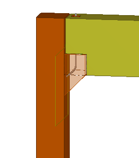
Example: Add a corbel connection using Corbel connection (14)
In this example, you will add a corbel connection between a column and a beam.
-
Click
the Applications & components button
 in the side pane to open the
Applications & components catalog.
in the side pane to open the
Applications & components catalog.
-
Select the secondary part (beam).
Tekla Structures automatically adds the corbel connection between the column and the beam when you select the beam.
Picture tab
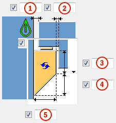
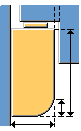
Use the Picture tab to control the corbel shape and dimensions, beam end shape and dimensions, and corbel side chamfers in Corbel connection (14).
When beam sloped, adjust
If the beam in the connection is sloped, define whether the beam or the corbel is cut.
When the beam end is cut, the corbel top stays horizontal. When the corbel is cut, the corbel top has the same slope as the beam.
Corbel dimensions and shape
|
Description |
|
|---|---|
|
1 |
Gap between the column and the beam. |
|
2 |
Gap between the corbel and the beam. |
|
3 |
Vertical corbel dimension. |
|
4 |
Beveled corbel dimension. |
|
5 |
Corbel width. |
|
Option |
Description |
|---|---|
|
|
Default Beveled corbel AutoDefaults can change this option. |
|
|
Beveled corbel |
|
|
Square corbel |
|
|
Rounded corbel |
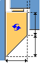
Corbel position
|
Description |
|
|---|---|
|
1 |
Horizontal corbel offset. |
|
2 |
Height of the beam cut. |
|
3 |
Gap between the corbel and extended beam. |
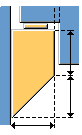
Beam end shape
You can fit the beam end to the column, or you can create a straight beam end.
|
Option |
Description |
Example |
|---|---|---|
|
|
Default Straight beam end AutoDefaults can change this option. |
|
|
|
Straight beam end |
|
|
|
Beam end is fit to the column based on the dimensions you define. Beam can extend symmetrically on both sides of the column, or with different dimensions. |
|
Corbel thickness
Define the distances from column edges to set the corbel thickness.
Corbel side chamfers
Define whether the corbel sides are chamfered. By default, no chamfers are created.
Parts tab
Use the Parts tab to control the corbel part properties and dimensions in Corbel connection (14).
Corbel parts
|
Part |
Description |
|---|---|
|
Bearing plate |
Bearing plate thickness. |
|
Cast unit |
Select whether cast unit is formed. |
|
Drainage hole |
Select whether drainage holes for each reinforcing bar are created in the bearing plate.
|
|
Bolt plate |
Bolt plate thickness. |
|
Nut |
Nut thickness. |
|
Option |
Description |
Default |
|---|---|---|
|
Pos_No |
Prefix and start number for the part position number. Some components have a second row of fields where you can enter the assembly position number. |
The default part start number is defined on the Components tab in . |
|
Material |
Material grade. |
The default material is defined in the Part material box on the Components tab in . |
|
Name |
Name that is shown in drawings and reports. |
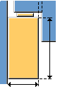
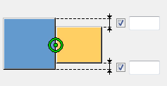
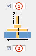
Bearing plate dimensions
|
Description |
|
|---|---|
|
1 |
Bearing plate distance from the column edge. |
|
2 |
Bearing plate distance from the corbel edges. |
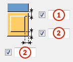
Nut and bolt plate dimensions
|
Description |
|
|---|---|
|
1 |
Nut width. |
|
2 |
Bolt plate width. |
Reinforcing bar tab
Use the Reinforcing bartab to control the reinforcing bar and fastening plate properties, and the bolt plate and fastening plate recesses in Corbel connection (14).
Reinforcing bar properties
|
Option |
Description |
|---|---|
|
Grade |
Strength of the steel used in the reinforcing bars. |
|
Size |
Diameter of the reinforcing bar. |
|
Bending radius |
Internal radius of the bends in the bar. |
|
Name |
Tekla Structures uses the name in drawings and reports. |
|
Class |
Use Class to group reinforcements. For example, you can display different reinforcement classes in different colors. |
|
Number of bars |
Select 1 Dowel to create one reinforcing bar. Select 2 Dowels to create two reinforcing bars. Then define the distance between the bars in the Bar distance field. |
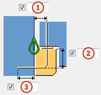
Reinforcing bar length
|
Description |
|
|---|---|
|
1 |
Distance between reinforcing bar center line and the column edge. |
|
2 |
Vertical length of the reinforcing bar inside the corbel. |
|
3 |
Length of the reinforcing bar inside the column. |
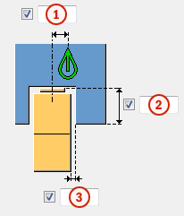
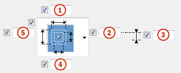
Recess for bolt plate and nut
|
Description |
|
|---|---|
|
1 5 |
Size of the bolt plate recess in the x direction. Size of the bolt plate recess in the y direction. |
|
2 4 |
Size of the nut recess in the y direction. Size of the nut recess in the x direction. |
|
3 |
Reinforcing bar offset. |
Reinforcing bar extra length

|
Description |
|
|---|---|
|
1 |
Extra length of the reinforcing bar. |
|
2 |
Length of the reinforcing bar inside the recess. |
Connecting devices
Define the connecting devices that connect the beam and the column.
|
Option |
Description |
|---|---|
|
|
Default One or two reinforcing bars bent to the same angle as the corbel bevel Available for bevel corbels. AutoDefaults can change this option. |
|
|
One or two reinforcing bars bent to the same angle as the corbel bevel Available for bevel corbels. |
|
|
One or two reinforcing bars Default for straight and rounded corbels. |
|
|
Two fastening plates Use custom components as fastening plates. |


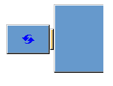
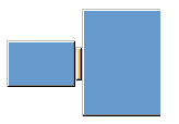
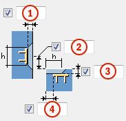
Recess for fastening plate
|
Description |
|
|---|---|
|
1 2 |
Depth of column recess. Depth of beam recess. |
|
3 4 |
Offset of column recess. Offset of beam recess. |
|
Column recess Beam recess |
Height and width of column and beam recess. |
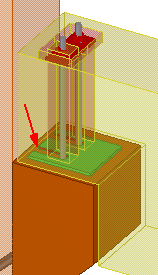
Using custom components as fastening plates
You can use custom components as fastening plates. Use the Column component and Beam component sections to define the fastening plates in the column and beam.
-
Select the following option in the Connecting devices list:

-
In the Custom list, select Yes.
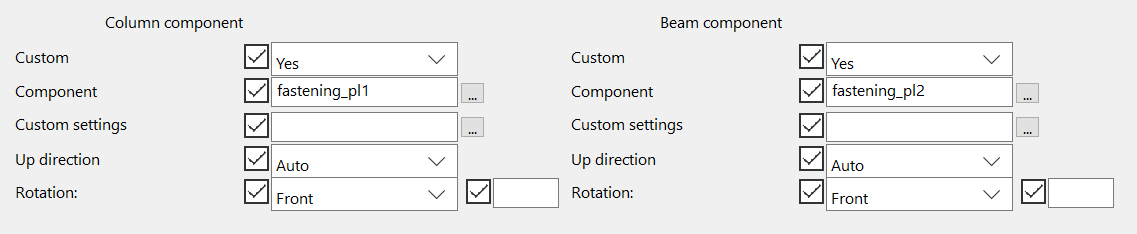
-
Click the ... button next to the Component field to open the Select component dialog.
-
Browse for the custom component you want to use as fastening plate.
The component you select must be a custom part and have two or more input points.
-
Select the component and click OK.
-
To use saved custom component properties, select the saved properties file in Custom settings.
-
If the direction or rotation of the fastening plate is not correct, select another option in the Up direction or Rotation list.
General tab
Click the link below to find out more:
Analysis tab
Click the link below to find out more: