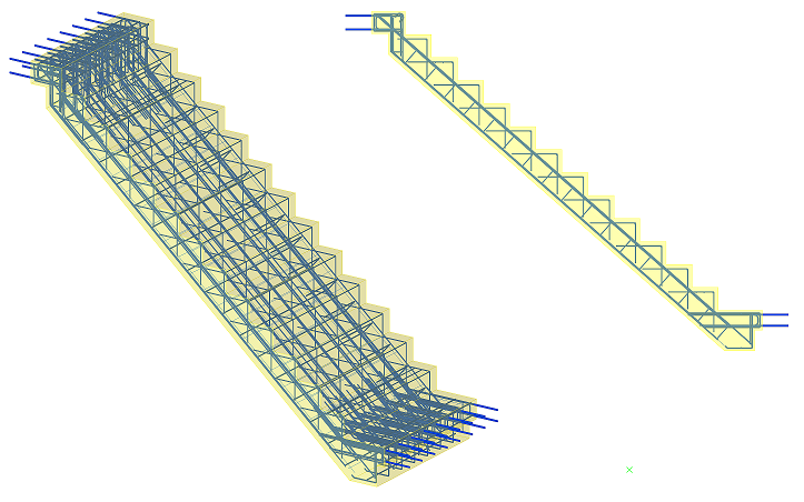
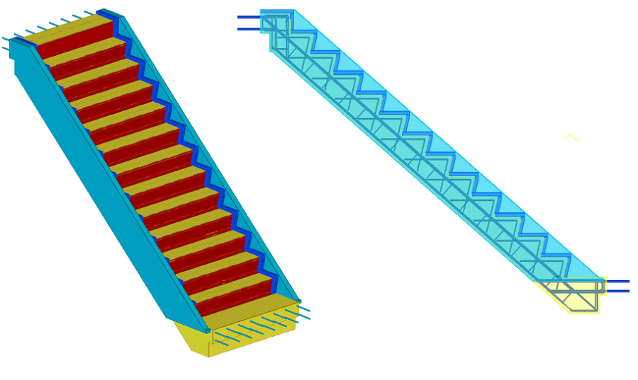
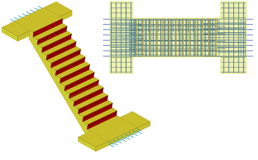
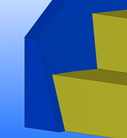
Reinforced concrete stair (95)
Reinforced concrete stair (95) creates reinforced concrete stairs.
Objects created
-
Stairs
-
Landings (optional)
-
Ridges (optional)
-
Stringers (optional)
-
Anti-skid (optional)
-
Main bars and stirrups of stair reinforcement (Bar A - Bar L tabs) (optional)
-
Meshes in stairs and landings (optional)
-
Mesh bars (optional)
-
Anchor bars (optional)
-
Landing end bars (optional)
Use for
| Situation | Description |
|---|---|
|
|
Reinforced concrete stairs. |
|
|
Reinforced concrete stairs with chamfered steps, ridges and stringers. |
|
|
Reinforced concrete stairs with reinforced landings. |
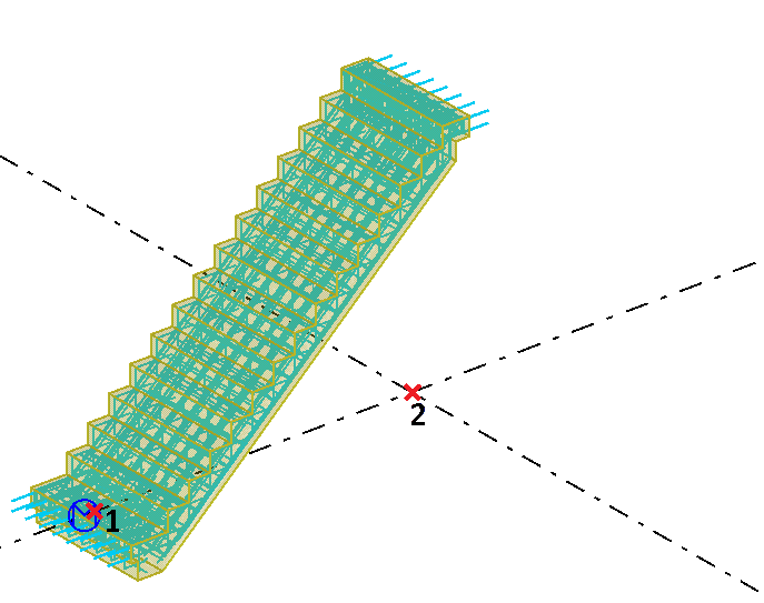
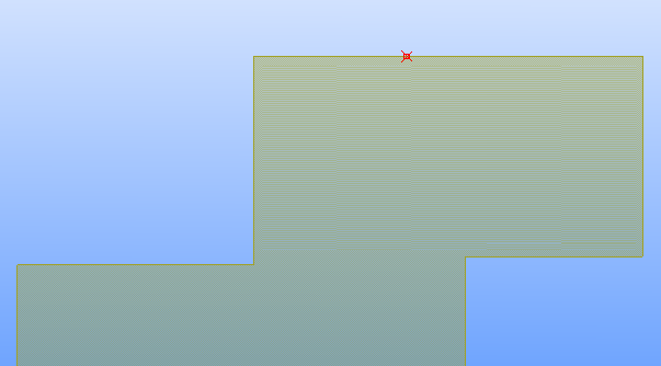
Selection order
-
Pick the first point to indicate the start point of the stairs.
-
Pick the second point to indicate the direction of the stairs.
-
Select any number of parts to be cut by the stairs (optional).
-
Click the middle mouse button to create the stairs.
Parameters tab
Use the Parameters tab to control the shape of the stairs, number of steps, stair creation method, and the stairs width.
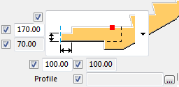
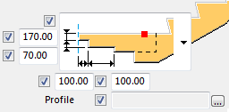
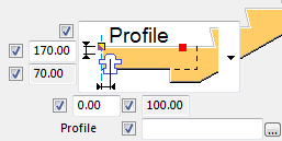
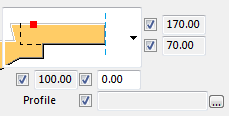
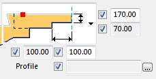
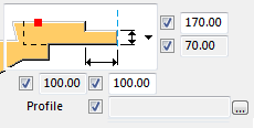
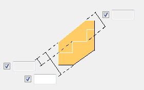
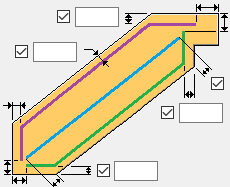
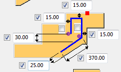
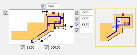
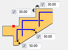
Stair dimensions
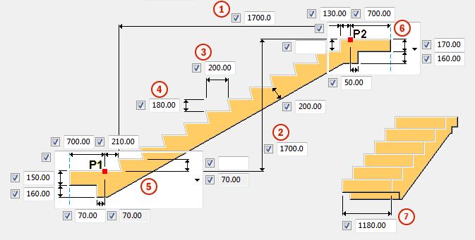
| Description | |
|---|---|
|
1 |
Horizontal dimension of the steps area |
|
2 |
Vertical dimension of the steps area |
|
3 |
Step length |
|
4 |
Step height |
|
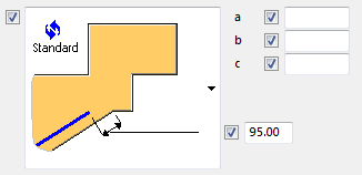
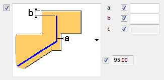
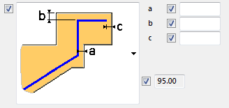
5 |
Shape options for stair bottom |
|
6 |
Shape options for stair top |
|
7 |
Stair width |
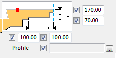
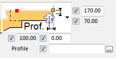
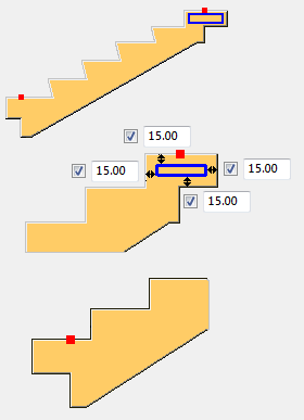
Start point position
Select the start point position of the polygon shape.
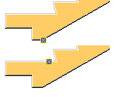
Note:
Start point position affects the bounding box of the cast-unit. Therefore it will affect drawing view orientation and numbering.
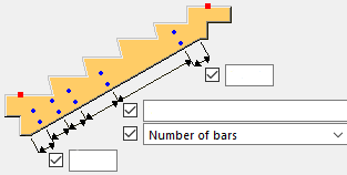
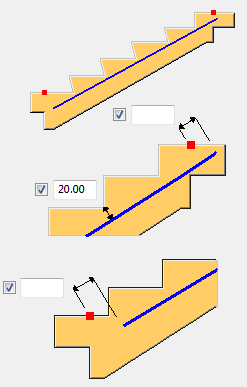
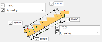
Stair creation method
| Option | Description |
|---|---|
|
P1 P2 step length |
Create stairs between points P1 and P2. Stair dimension are defined by the distance between P1 and P2 and step length. |
|
P1 P2 step height |
Create stairs between points P1 and P2. Stair dimension are defined by the distance between P1 and P2 and step height. |
|
P1 step length step height N steps |
Create stairs from point P1 to point P2. Stair dimensions are defined by P1 and step height, length and number of steps. |
|
P2 step length step height N steps |
Create stairs from point P1 to point P2. Stair dimensions are defined by P2 and step height, length and number of steps. |
|
P1 horizontal and vertical step distance |
Create stairs from point P1 to point P2. Stair dimensions are defined by P1 and horizontal and vertical step distance. |
|
P2 horizontal and vertical step distance |
Create stairs from point P1 to point P2. Stair dimensions are defined by P2 and horizontal and vertical step distance. |
Parts tab
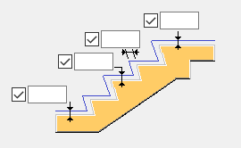
Use the Parts tab to control the material, name, class, positioning, cast unit type and step chamfering.
Step chamfer settings
| Option | Description |
|---|---|
|
Middle for all |
All steps are chamfered according to the Middle steps settings. |
|
Bottom different |
Bottom step is chamfered according to the 1st step at bottom settings. All other steps are chamfered according to the Middle steps settings. |
|
Top different |
Top step is chamfered according to the Last top step settings. All other steps are chamfered according to the Middle steps settings. |
|
Bottom and top different |
Bottom step is chamfered according to the 1st step at bottom settings. Top step chamfered are according to the Last top step settings. All other steps are chamfered according to the Middle steps settings. |
Step chamfer settings are set in the same way for 1st step at bottom, Middle steps, and Last top step.
| Option | Description |
|---|---|
|
|
Size of step cut is defined by the distance. |
|
|
Size of step cut is defined by the angle. |
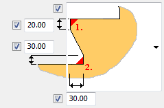
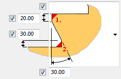
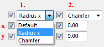
Corner chamfer types
Corner chamfers 1. and 2. can be defined by the Radius x or by the sides of the Chamfer x, y.
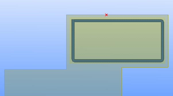
Create finished floor level
Select whether to create finished floor level. The finished floor level is defined by a polygon created from an offset stairs polygon and it is used for drawings.
Define the profile, properties, and offsets of the dummy part that is created at each polygon vertex, and the position in depth. You can define different offsets for floor level profiles for the steps, and the top and bottom landing, and the vertical cover thickness.
Stairs and landings tab
Use the Stairs and landings tab to control the size and type of the bottom landing and the top landing.
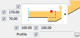
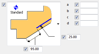
Bottom landing cut option
| Option | Description |
|---|---|
|
|
Bottom landing with no cut. |
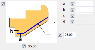
|
|
Bottom landing with cut defined by its length and distance from the top side of landing. |
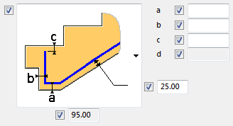
|
|
Bottom landing with cut defined by its length and distance from the bottom side of landing. |
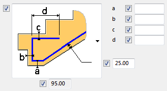
|
|
Bottom landing with L shape cut defined by its three dimensions and distance from the top side of landing. |
|
|
Bottom landing cut defined by a profile and its position in landing. |
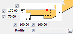
Top landing cut option
| Option | Description |
|---|---|
|
|
Top landing with no cut. |
|
|
Top landing with cut defined by its length and distance from the top side of landing. |
|
|
Top landing with cut defined by its length and distance from the bottom side of landing. |
|
|
Top landing with L shape cut defined by its three dimensions and distance from the top side of landing. |
|
|
Top landing cut defined by a profile and its position in landing. |
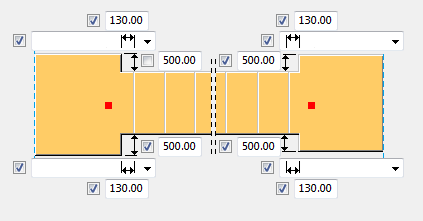
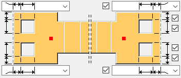
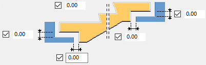
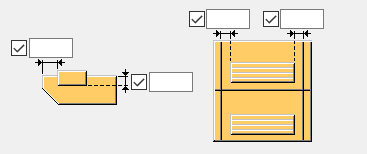
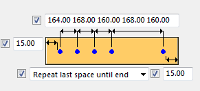
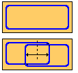
Landing dimensioning and openings
| Description | |
|---|---|
|
|
Use the top view setting to define the dimensions of the bottom landing and the top landing. |
|
|
Use the top view setting to define two openings for the bottom and the top landing. The following rebars avoid the created openings: anchor and Z anchor bars, mesh bars, landing end bars, and A, B, C, E, G, K bars. |
|
Extra landings |
Define an individual name and class for the extra landing parts. |
|
|
Define the gaps on the sides of the landings. |
Recesses and holes
|
Option |
Description |
|---|---|
|
|
No hole or recess |
|
|
Hole |
|
|
Recess at the top face |
|
|
Recess at the bottom face |


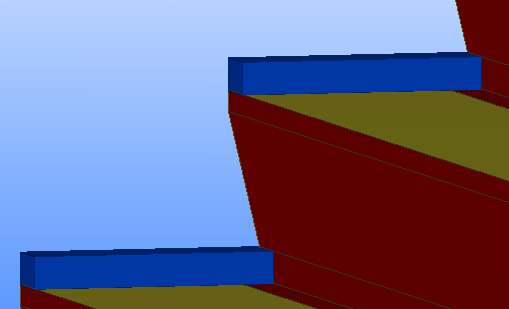
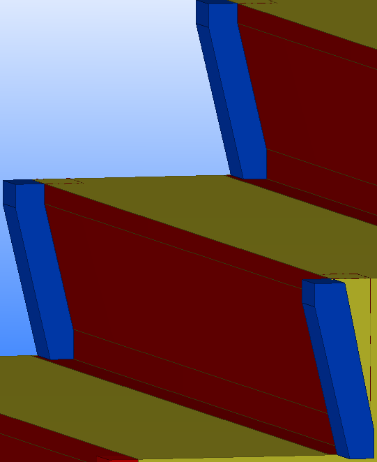
Ridges tab
Use the Ridges tab to create horizontal and/or vertical ridges on both sides or only on one side of the stairs.
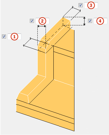
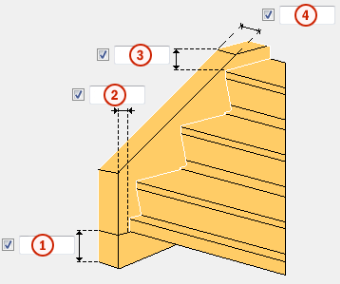
Dimensions
| Description | |
|---|---|
| 1 |
Thickness of the vertical ridge. |
| 2 |
Width of the vertical ridge. |
| 3 |
Width of the horizontal ridge. |
| 4 |
Thickness/height of the horizontal ridge. |
Horizontal ridges
| Option | Description |
|---|---|
| Create |
Define whether horizontal ridges are created.
|
| Create at foot |
Define whether horizontal ridges are created at the foot of the stairs. This option works in the same way as the Create option. |
|
Chamfering
|
1 Inside chamfer: Select the type of the inside chamfer and enter the required dimensions. 2 Corner chamfer: Select the type of the corner chamfer and enter the required dimensions. 3 Slope: Set the slope as an angle or a dimension. The slope makes the ridge inclined. |
| Foot corner chamfer |
Define whether corner chamfers are created at the stair foot. |
Vertical ridges
| Option | Description |
|---|---|
|
Create |
Define whether vertical ridges are created. |
|
Slope |
Set the slope as an angle or a dimension. The slope makes the ridge inclined. |
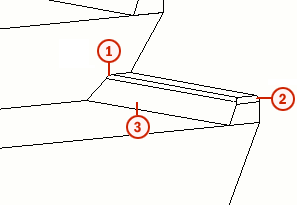
Stringers tab
Use the Stringers tab to create the stringers and ridges on the left, right, or both sides of the stairs.
| Description | ||
|---|---|---|
|
|
1 |
Height of the stringer bottom ridge. |
| 2 |
Horizontal offset of the bottom ridge from the bottom step. |
|
| 3 |
Height of the stringer top ridge. |
|
| 4 |
Width of the stringer. |
|
| Slope |
Use to incline the inner surface of the stringers.
You can define the slope using an angle or a dimension. |
|
| Inside chamfer |
Define whether the inside edge of stringer is chamfered or not. |
|
| Outside chamfer |
Define whether the outside edge of stringer is chamfered or not. |
|
Stringer height
Stringer height based on the total height or distance from inner/outer step corner.
Stringer bars tab
Use the Stringer bars tab to create reinforcements in the stringers.
|
Option |
Description |
|---|---|
|
|
Define the spacing of bars and the concrete cover thicknesses. |
|
Create |
Select to create the group of bars. |
|
Grade |
Strength of the steel used in the reinforcing bars. |
|
Size |
Diameter of the reinforcing bar. |
|
Radius |
Internal radius of the bends in the bar. |
|
Prefix |
Prefix for the rebar position number. |
|
Start number |
Start number for the rebar position number. |
|
Class |
Reinforcement class. |
|
Name |
The name used in drawings and reports. |
|
Comment |
Enter a comment UDA, if needed. |
Anti-skid tab
Use the Anti-skid tab to create slip resistant surfaces.
| Option | Description |
|---|---|
|
Creation anti-skid |
Define whether anti-skids are created. |
|
First bottom anti-skid |
Define the material, name and class of the anti-skid profile at the bottom. |
|
Last top anti-skid |
Define the material, name and class of the anti-skid profile at the top. |
|
Create anti-skid on foot/top |
Define whether anti-skids are created at the stair foot/top. |
|
Create cutout |
Define whether you want to create cutouts with the anti-skid profile. By default, the cutouts are not created. |
|
Include in cast unit |
Define whether anti-skids are included in the cast unit. |
|
Profile |
Define the anti-skid profile by selecting it from the profile catalog. |
|
Rotation |
Select an option to rotate the anti-skid profile. |
|
Offsets |
Define the anti-skid profile offsets on the steps.
|
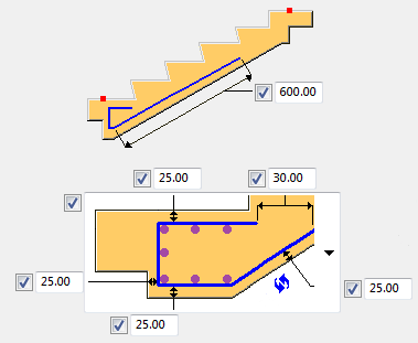
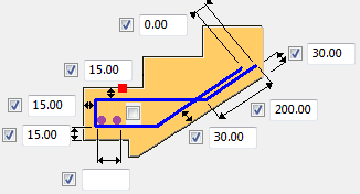
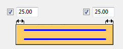
Bar A tab
Use the Bar A tab to define the geometry, concrete cover thickness, reinforcing bar spacing, and reinforcing bar properties of a stair reinforcing bar group.
| Option | Description |
|---|---|
|
|
Geometry and concrete cover thickness. |
|
|
Spacing, number of bars, and concrete cover thickness of the reinforcing bar group. |
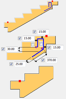
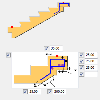
Bar B tab
Use the Bar B tab to define the geometry, concrete cover thickness, reinforcing bar spacing, and reinforcing bar properties of a stair reinforcing bar group.
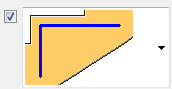
Bottom ending options
Define geometry and concrete cover thickness of the bar B bottom ending.
| Option | Description |
|---|---|
|
|
Bar B simple bottom ending. |
|
|
Bar B bottom ending bent once to fit the bottom footing of the stairs. |
|
|
Bar B bottom ending bent twice to fit the bottom footing of the stairs. |
|
|
Bar B bottom ending bent up to three times to fit the bottom footing of the stairs. |
Top ending options
Define geometry and concrete cover thickness of the bar B top ending.
| Option | Description |
|---|---|
|
|
Bar B simple top ending. |
|
|
Bar B top ending bent once to fit the top geometry of the stairs. |
|
|
Bar B top ending bent twice to fit the top geometry of the stairs. Last leg length is defined by the cover thickness. |
|
|
Bar B top ending bent twice to fit the top geometry of the stairs. |
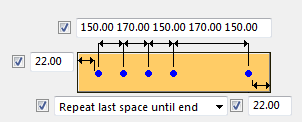
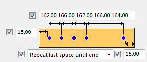
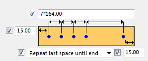
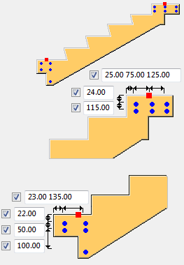
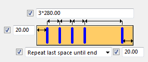
Reinforcing bar spacing
| Option | Description |
|---|---|
|
|
Spacing, number of bars, and concrete cover thickness of the reinforcing bar group. |
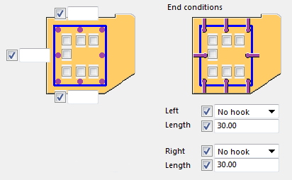
Bar C tab
Use the Bar C tab to define the geometry, concrete cover thickness, reinforcing bar spacing, and reinforcing bar properties of a stair reinforcing bar group.
| Option | Description |
|---|---|
|
|
Geometry and concrete cover thickness. |
|
|
Define which extra side bars are created, their end conditions, and the concrete cover. |
|
|
Spacing, number of bars, and concrete cover thickness of the reinforcing bar group. |
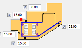
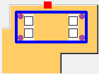
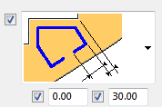
Additional bars
| Option | Description |
|---|---|
|
|
The purple color in the dialog represents the additional bars. |
|
|
Define whether to create the additional bars. Select the checkboxes next to the purple points. |
|
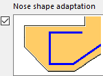
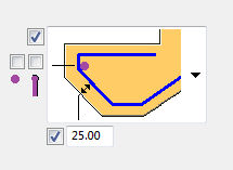
|
Select the nose shape adaptation. The first checkbox (the dot on the left) creates the additional bar and the second creates a hook on it. |
|
|
Cover thickness of the reinforcing bars. |
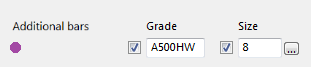

Additional bar properties
|
Option |
Description |
|---|---|
|
Grade |
Strength of the steel used in the reinforcing bars. |
|
Size |
Diameter of the reinforcing bar. |
|
Class |
Reinforcement class. |
|
Prefix |
Prefix for the rebar position number. |
|
Start number |
Start number for the rebar position number. |
|
Comment |
Enter a comment UDA, if needed. |
|
Name |
The name is used in drawings and reports. |
Bar D tab
Use the Bar D tab to define the geometry, concrete cover thickness, reinforcing bar spacing, and reinforcing bar properties of a stair reinforcing bar group.
| Option | Description |
|---|---|
|
|
Geometry and concrete cover thickness. |
|
|
Spacing, number of bars, and concrete cover thickness of the reinforcing bar group. |

Additional bars
Additional bars are straight bars crossing bar D. You can create up to four additional bars.
| Option | Description |
|---|---|
|
|
The purple color in the dialog represents the additional bars. |
|
|
Define whether to create the additional bars. Select the checkboxes next to the purple points. |
|
|
Cover thickness of the reinforcing bars. |
Additional bar properties
|
Option |
Description |
|---|---|
|
Grade |
Strength of the steel used in the reinforcing bars. |
|
Size |
Diameter of the reinforcing bar. |
|
Class |
Reinforcement class. |
|
Prefix |
Prefix for the rebar position number. |
|
Start number |
Start number for the rebar position number. |
|
Comment |
Enter a comment UDA, if needed. |
|
Name |
The name is used in drawings and reports. |
Bar E tab
Use the Bar E tab to define the geometry, concrete cover thickness, reinforcing bar spacing and reinforcing bar properties of a stair reinforcing bar group.
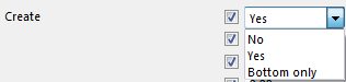
Create options
| Option | Description |
|---|---|
| No |
Bar is not created.
|
| Stirrups |
Bar is created as stirrups.
|
| Pin |
Bar is created as pin.
|
| Option | Description |
|---|---|
|
|
Geometry and concrete cover thickness. |
|
|
Spacing, number of bars, and concrete cover thickness of the reinforcing bar group. |
|
|
Shape of the stirrups. |
|
Parallel with step slope |
Yes Create parallel with sloped step shape. |
|
No Create as a rectangle. |
Additional bars
Additional bars are straight bars crossing bar E. You can create up to four additional bars.
| Option | Description |
|---|---|
|
|
The purple color in the dialog represents the additional bars. |
|
|
Define whether to create the additional bars. Select the checkboxes next to the purple points. |
|
|
Cover thickness of the reinforcing bars. |
Additional bar properties
|
Option |
Description |
|---|---|
|
Grade |
Strength of the steel used in the reinforcing bars. |
|
Size |
Diameter of the reinforcing bar. |
|
Class |
Reinforcement class. |
|
Prefix |
Prefix for the rebar position number. |
|
Start number |
Start number for the rebar position number. |
|
Comment |
Enter a comment UDA, if needed. |
|
Name |
The name is used in drawings and reports. |
Bar F tab
Use the Bar F tab to define the geometry, concrete cover thickness, reinforcing bar spacing and reinforcing bar properties of a stair reinforcing bar group.
| Option | Description |
|---|---|
|
|
Geometry and concrete cover thickness. |
|
|
Spacing, number of bars, and concrete cover thickness of the reinforcing bar group. |
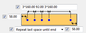
Bar G tab
Use the Bar G tab to define the geometry, concrete cover thickness, reinforcing bar spacing, and reinforcing bar properties of a stair reinforcing bar group.
| Option | Description |
|---|---|
|
|
Geometry and concrete cover thickness. |
|
|
Spacing, number of bars, and concrete cover thickness of the reinforcing bar group. |
Additional bars
Additional bars are straight bars crossing bar G. You can create up to four additional bars.
| Option | Description |
|---|---|
|
|
The purple color in the dialog represents the additional bars. |
|
|
Define whether to create additional bars. Select the checkboxes next to the purple points. |
|
|
Cover thickness of the reinforcing bars. |

Additional bar properties
|
Option |
Description |
|---|---|
|
Grade |
Strength of the steel used in the reinforcing bars. |
|
Size |
Diameter of the reinforcing bar. |
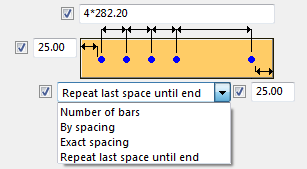
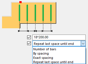
|
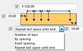
Spacing |
Select whether the spacing is based on the distance between the bars (By spacing) or on the number of bars (Number of bars). Enter the value in the next field. |
|
Class |
Reinforcement class. |
|
Prefix |
Prefix for the rebar position number. |
|
Start number |
Start number for the rebar position number. |
|
Comment |
Enter a comment UDA, if needed. |
|
Name |
The name is used in drawings and reports. |
Bar H tab
Use the Bar H tab to define the geometry, concrete cover thickness, reinforcing bar spacing, and reinforcing bar properties of a stair reinforcing bar group.
Create option
| Option | Description |
|---|---|
|
|
|
Geometry option
| Option | Description |
|---|---|
|
|
Two bent reinforcing bar groups. Define geometry and concrete cover thickness. |
|
|
Top reinforcing bar group is straight, bottom reinforcing bar group is bent on both sides. Define geometry and concrete cover thickness. |
|
|
Two straight reinforcing bar groups. Define geometry and concrete cover thickness. |
|
|
Two reinforcing bar groups. Define geometry and concrete cover thickness. |
|
|
Reinforcing bar group that is bent on one side. Define the concrete cover thickness and whether to create hooks. You can create multiple overlapping stirrups in a row. Define the overlap dimension and the number of stirrups.
|
Spacing
| Option | Description |
|---|---|
|
|
Define the spacing separately for bottom and top rebars. |
Properties
You can define separate properties for bottom and top rebars.
|
Option |
Description |
|---|---|
|
Grade |
Strength of the steel used in the reinforcing bars. |
|
Size |
Diameter of the reinforcing bar. |
|
Bend radius |
Internal radius of the bends in the bar. |
|
Comment |
Enter a comment UDA, if needed. |
|
Name |
The name used in drawings and reports. |
|
Class |
Reinforcement class. |
|
Prefix |
Prefix for the rebar position number. |
|
Start number |
Start number for the rebar position number. |
Bar I tab
Use the Bar I tab to define the geometry, concrete cover thickness, reinforcing bar spacing, and reinforcing bar properties of a stair reinforcing bar group.
| Option | Description |
|---|---|
|
|
Positioning, spacing, and concrete cover thickness. |
|
|
Concrete cover thickness of the reinforcing bar groups. |

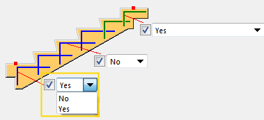
Bar J tab
Use the Bar J tab to define the geometry, concrete cover thickness, reinforcing bar spacing, and reinforcing bar properties of a stair reinforcing bar group. You can create several bar J reinforcing bar groups. Each group has its own color representation on the Bar J tab.
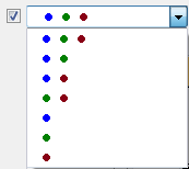
Color group options
| Option | Description |
|---|---|
|
|
Use the color group option to define which combination of bar J reinforcing bar groups (blue, green, brown) is created. |
| Option | Description |
|---|---|
|
|
Positioning and concrete cover thickness for reinforcing bar groups based on the color representation. |
|
|
Concrete cover thickness for all reinforcing bar groups. |
Bar K tab
Use the Bar K tab to define the geometry, concrete cover thickness, reinforcing bar spacing, and reinforcing bar properties of a stair reinforcing bar group.
| Option | Description |
|---|---|
|
|
Select the geometry and define the concrete cover thickness. |
|
|
Spacing, number of bars, and concrete cover thickness of the reinforcing bar group. |
Additional bars
Additional bars are straight bars crossing bar K. You can create up to three additional bars.
| Option | Description |
|---|---|
|
|
The purple color in the dialog represents the additional bars. |
|
|
Define whether to create additional bars by selecting the checkboxes next to the purple points. |
|
|
Cover thickness of the reinforcing bars. |

Additional bar properties
|
Option |
Description |
|---|---|
|
Grade |
Strength of the steel used in the reinforcing bars. |
|
Size |
Diameter of the reinforcing bar. |
|
Spacing |
Select whether the spacing is based on the distance between the bars (By spacing) or on the number of bars (Number of bars). Enter the value in the next field. |
|
Class |
Reinforcement class. |
|
Prefix |
Prefix for the rebar position number. |
|
Start number |
Start number for the rebar position number. |
|
Comment |
Enter a comment UDA, if needed. |
|
Name |
The name is used in drawings and reports. |
Top landing stirrups tab
Use the Top landing stirrups tab to define the geometry, concrete cover thickness, reinforcing bar spacing, and properties of the top landing stirrups.
Create landing stirrups
| Option | Description |
|---|---|
|
Create |
|
Top landing stirrups geometry option
| Option | Description |
|---|---|
|
|
Two bent reinforcing bar groups. Define the geometry and concrete cover thickness. |
|
|
Top reinforcing bar group is straight, bottom reinforcing bar group is bent on both sides. Define the geometry and concrete cover thickness. |
|
|
Two straight reinforcing bar groups. Define the geometry and concrete cover thickness. |
|
|
Two reinforcing bar groups. Define the geometry and concrete cover thickness. |
|
|
Reinforcing bar group that is bent on one side. Define the concrete cover thickness and whether to create hooks. You can create multiple overlapping stirrups in a row. Define the overlap dimension and the number of stirrups.
|

Bar spacing and concrete cover thickness
| Option | Description |
|---|---|
|
|
Define the spacing and number of bars in the reinforcing bar group. |
|
|
Define the concrete cover thickness. |
Properties
| Option | Description |
|---|---|
|
Grade |
Strength of the steel used in the reinforcing bars. |
|
Size |
Diameter of the reinforcing bar. |
|
Bend radius |
Internal radius of the bends in the bar. |
|
Comment |
Enter a comment UDA, if needed. |
|
Name |
The name is used in drawings and reports. |
|
Class |
Reinforcement class. |
|
Prefix |
Prefix for the rebar position number. |
|
Start number |
Start number for the rebar position number. |
Bottom landing stirrups tab
Use the Bottom landing stirrups tab to define the geometry, concrete cover thickness, reinforcing bar spacing, and properties of the bottom landing stirrups.
Create landing stirrups
| Option | Description |
|---|---|
|
Create |
|
Bottom landing stirrups geometry option
| Option | Description |
|---|---|
|
|
Two bent reinforcing bar groups. Define the geometry and concrete cover thickness. |
|
|
Top reinforcing bar group is straight, bottom reinforcing bar group is bent on both sides. Define the geometry and concrete cover thickness. |
|
|
Two straight reinforcing bar groups. Define the geometry and concrete cover thickness. |
|
|
Two reinforcing bar groups. Define the geometry and concrete cover thickness. |
|
|
Reinforcing bar group that is bent on one side. Define the concrete cover thickness and whether to create hooks. You can create multiple overlapping stirrups in a row. Define the overlap dimension and the number of stirrups.
|
Bar spacing and concrete cover thickness
| Option | Description |
|---|---|
|
|
Define the spacing and number of bars in the reinforcing bar group. |
|
|
Define the concrete cover thickness. |
Properties
| Option | Description |
|---|---|
|
Grade |
Strength of the steel used in the reinforcing bars. |
|
Size |
Diameter of the reinforcing bar. |
|
Bend radius |
Internal radius of the bends in the bar. |
|
Comment |
Enter a comment UDA, if needed. |
|
Name |
The name is used in drawings and reports. |
|
Class |
Reinforcement class. |
|
Prefix |
Prefix for the rebar position number. |
|
Start number |
Start number for the rebar position number. |
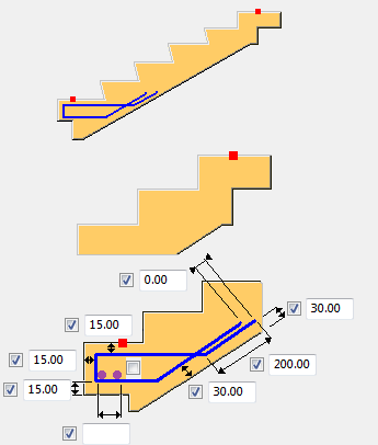
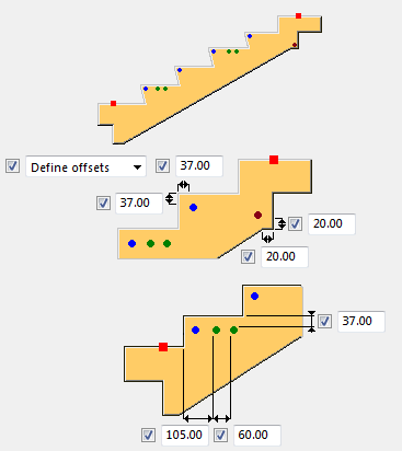
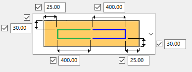
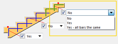
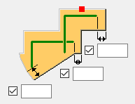
Bar L tab
Use the Bar L tab to define the geometry, concrete cover thickness, reinforcing bar spacing, and reinforcing bar properties of a stair reinforcing bar group.
| Option | Description |
|---|---|
|
|
Define whether an L shaped reinforcing bar group is created at the stair footing. |
|
|
Define whether an L shaped reinforcing bar group is created at the stair top or whether all bars are created with the same geometry. |
|
|
Define offsets for the reinforcing bar groups in the two top steps. |
|
|
Define whether reinforcing bars are created between the top and bottom step. |
|
|
Define geometry for reinforcing bar groups in all steps, except for the two top steps. |
|
|
Spacing, number of bars and concrete cover thickness of the reinforcing bar group. |
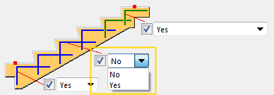
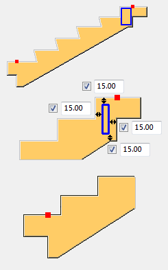
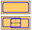
Geometry options
The geometry options affect the middle and the bottom steps.
| Option | Description |
|---|---|
|
|
L shape reinforcing bar groups. |
|
|
L shape reinforcing bar groups with hooks. |
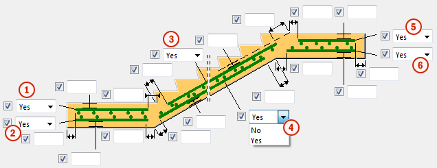
Mesh picture tab
Use the Mesh picture tab to define bottom landing meshes, stair meshes, and top landing meshes.
Side view
| Description | |
|---|---|
|
1 |
Bottom landing mesh (top). Define offsets and cover thickness of the mesh. |
|
2 |
Bottom landing mesh (bottom). Define offsets and cover thickness of the mesh. |
|
3 |
Stair mesh (top). Define offsets and cover thickness of the mesh. |
|
4 |
Stair mesh (bottom). Define offsets and cover thickness of the mesh. |
|
5 |
Top landing mesh (top). Define offsets and cover thickness of the mesh. |
|
6 |
Top landing mesh (bottom). Define offsets and cover thickness of the mesh. |
Top view
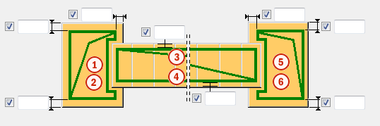
| Description | |
|---|---|
|
1 |
Cover thickness of bottom landing mesh (top). |
|
2 |
Cover thickness of bottom landing mesh (bottom). |
|
3 |
Cover thickness of stair mesh (top). |
|
4 |
Cover thickness of stair mesh (bottom). |
|
5 |
Cover thickness of top landing mesh (top). |
|
6 |
Cover thickness of top landing mesh (bottom). |
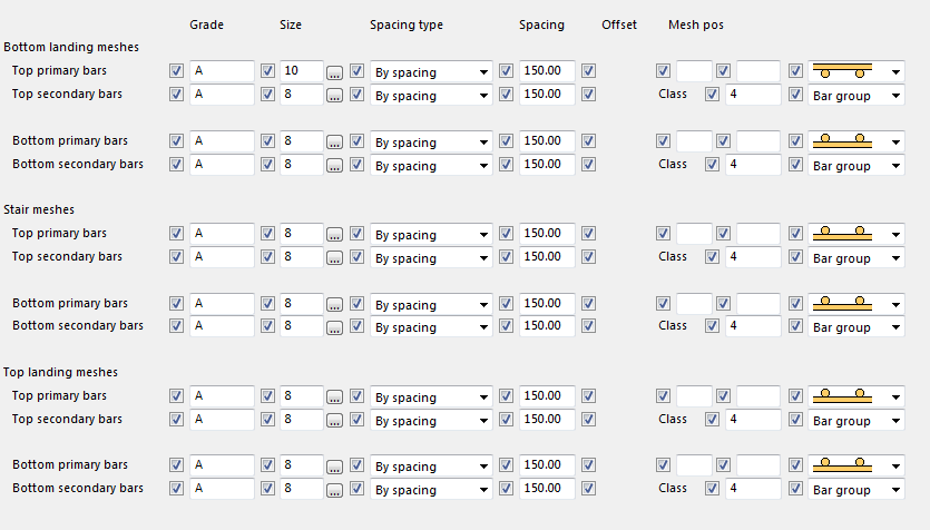
Mesh attributes tab
Use the Mesh attributes tab with the Mesh picture tab to define the properties, positioning and creation type of bottom landing meshes, stair meshes, and top landing meshes.
Cross bar location
| Description | |
|---|---|
|
|
Cross bar above. |
|
|
Cross bar below. |


Creation type
| Description | |
|---|---|
|
|
Create mesh as reinforcement mesh. |
|
|
Create mesh as two independent reinforcing groups. |


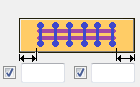
Mesh bars tab
Use the Mesh bars tab to define the geometry, concrete cover thickness, reinforcing bar spacing, and reinforcing bar properties of the mesh bars in the top and bottom landing. You can create up to three reinforcing bar groups.
| Description | ||
|---|---|---|
|
|
1 |
Cover thicknesses of all mesh bar groups in the stair bottom landing. Use the color representation in the dialog. |
| 2 |
Vertical cover thicknesses of all mesh bar groups in the stair bottom landing. Use the color representation in the dialog. |
|
| 3 |
Cover thicknesses of all mesh bar groups in the stair top landing. Use the color representation in the dialog. |
|
| 4 |
Vertical cover thicknesses of all mesh bar groups in the stair top landing. Use the color representation in the dialog. |
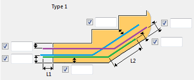
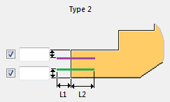
Bottom anchor bars tab
Use the Bottom anchor bars tab to define the geometry, concrete cover thickness, reinforcing bar spacing, and reinforcing bar properties of the bottom anchor bars. You can create up to three reinforcing bar groups.
Creation type
| Option | Description |
|---|---|
| No |
No reinforcing bar group created. |
| Type 1 |
L shape anchor reinforcing bar group.
|
| Type 2 |
Simple straight anchor reinforcing bar group.
|
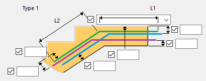
Top anchor bars tab
Use the Top anchor bars tab to define the geometry, concrete cover thickness, reinforcing bar spacing, and reinforcing bar properties of the top anchor bars. You can create up to three reinforcing bar groups.
Creation type
| Option | Description |
|---|---|
| No | No reinforcing bar group created. |
| Type 1 |
L shape anchor reinforcing bar group.
|
| Type 2 |
Simple straight anchor reinforcing bar group.
|
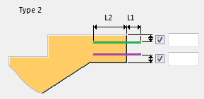
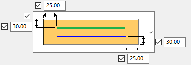
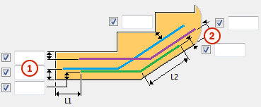
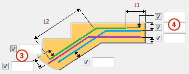
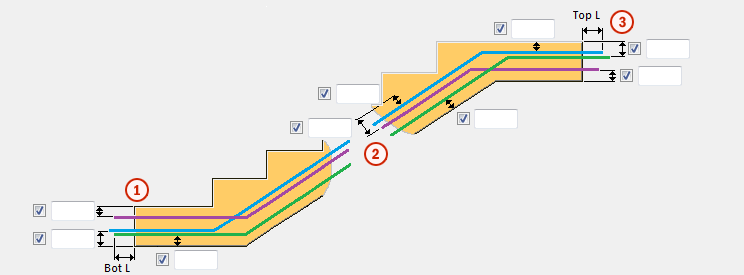
Z anchor bars tab
Use the Z anchor bars tab to define the geometry, concrete cover thickness, reinforcing bar spacing, and reinforcing bar properties of the Z anchor bars. You can create up to three reinforcing bar groups.
| Description | |
|---|---|
|
1 |
Cover thicknesses of all Z anchor bar groups in the stair bottom landing. Use the color representation in the dialog. |
|
2 |
Vertical cover thicknesses of all Z anchor bar groups in the stair main part. Use the color representation in the dialog. |
|
3 |
Cover thicknesses of all Z anchor bar groups in the stair top landing. Use the color representation in the dialog. |
|
Bot L |
Length of the Z anchor bars that extend from the stair bottom landing. |
|
Top L |
Length of the Z anchor bars that extend from the stair top landing. |
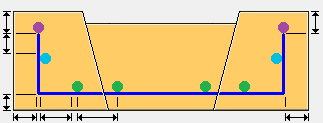
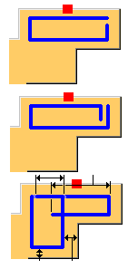
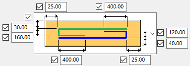
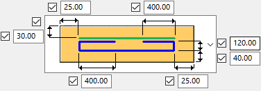
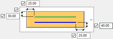
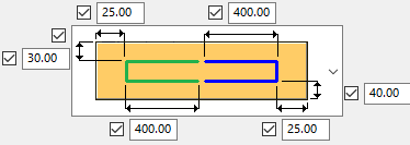
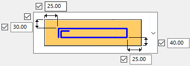
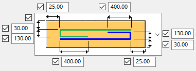
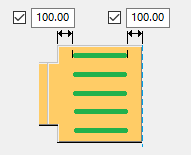
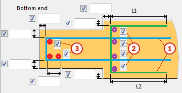
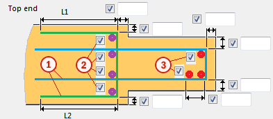
Landing end bars tab
Use the Landing end bars tab to reinforce the stair landings and to define the geometry, concrete cover thickness, reinforcing bar spacing, and bar properties of the landing end bars.
Bottom end
Reinforcement of bottom landing.
| Description | |
|---|---|
|
1 |
Landing end bars. U-shape geometry follows the shape of the landing based on the defined cover thicknesses. Color representation in the picture: blue, green. |
|
2 |
Define whether to create extra cross bars. Select the checkboxes next to the purple points. |
|
3 |
Define whether to create extra cross bars. Select the checkboxes next to the red points. |
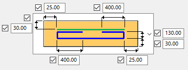
Top end
Reinforcement of top landing.
| Description | |
|---|---|
|
1 |
Landing end bars. U-shape geometry follows the shape of the landing based on defined cover thicknesses. Color representation in the picture: blue, green. |
|
2 |
Define whether to create extra cross bars. Select the checkboxes next to purple points. |
|
3 |
Define whether to create extra cross bars. Select the checkboxes next to red points. |
Side cover thickness
| Option | Description |
|---|---|
|
|
Side cover thickness of all reinforcing bar groups defined on the Landing end bars tab. |
UDA tab
Use the UDA tab to define user-defined attributes for the stairs. You can define multiple UDAs. UDAs can be used as filters, and they can be displayed in drawings and reports.
Configuration tab
Use the Configuration tab to define the default cover thicknesses and bending radiuses of all reinforcing bars created by Reinforced concrete stair (95).
General cover thickness for reinforcing bar groups A - C
Define the default cover thickness for reinforcing bar groups A - C.
| Option | Description |
|---|---|
|
Value |
Default cover thickness defined by a value. |
|
Rebar diameter |
Default cover thickness multiplied by reinforcing bar diameter. |
General cover thickness for reinforcing bar groups D - L
Define the default cover thickness for reinforcing bar groups D - L and all reinforcing bars except the reinforcing bar groups A - C and meshes.
| Option | Description |
|---|---|
|
Value |
Default cover thickness defined by a value. |
|
Rebar diameter |
Default cover thickness multiplied by reinforcing bar diameter. |
Bending radius
Define the default bending radius of all reinforcing bars.
| Option | Description |
|---|---|
|
Rebar_database.inp |
Default bending radius defined by the rebar_database.inp file. |
|
Relative to diameter |
Default bending radius according to the reinforcing bar diameter. |
|
Bending radius |
Default bending radius defined by value. |
Mesh cover thickness
Define the default cover thickness for the meshes created by Reinforced concrete stair (95).