Cut objects with a polygon, line, or part
Use polygon cuts, lines cuts, or part cuts to shape a part in a model.
If you need to modify the length of a part, do not use cuts but move the part handles. In addition to cuts, you can use the Fit part end command to adjust the part end.
Note:
Do not use cuts to cut a part into two. Numbering, material lists and drawings will consider the part as one, not as two separate parts.
Do not use cuts to shorten steel parts because cuts are not taken into account in LENGTH_GROSS, which is often used in steel material lists.
Cut objects with a polygon
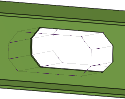
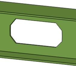
Use a polygon cut to cut a part, or a rebar set, with a closed polygon, perpendicular to the plane that is defined by the points you pick. Tekla Structures displays the cut using dash-and-dot lines.
The depth of the cut is calculated automatically based on the dimensions of the object to be cut. The Polygon cut command automatically extends the cut slightly (3 mm) outside of the part face in depth direction.
Tekla Structures uses the parametric profile BL to create polygonal cuts.
Tip:
To make it easier to pick the points for a polygon cut in a 3D view on a correct plane, use the command to create a suitable view. The command creates views that have view planes along the main axes (x,y,z) of the selected part.
-
Pick
points to outline the polygon to be used for cutting.
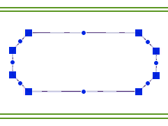
When defining the polygon, do not place the cut edges exactly at the same location as the edge of the part to be cut, as it can be unclear whether the edge should be cut away or not.
-
Click the middle mouse button to close the polygon and to cut the object.
If you need to modify the cut shape, use direct modification or handles to add or remove points, to add or change chamfers, or move an edge.
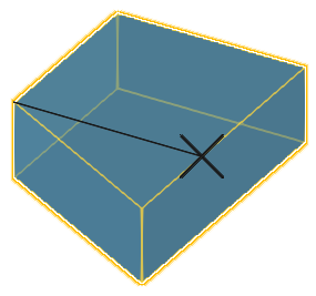
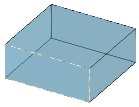
Cut objects with a line
Use line cuts to shape a beam or a column, or to cut a plate, a slab, an item, or a rebar set. A line cut creates a cutting plane, perpendicular to the view plane that passes through the two points you pick. You can use the line cut to cut the end of a part, or the side of a part, for example to make a part narrower. Tekla Structures displays the cut using dash-and-dot lines.
You can have several line cuts to one part end.
Tip:
To make it easier to pick the points for the cutting line, ensure that you are working in a view with a suitable view plane.
-
In many cases you can create a view with a suitable view plane by using the command. The command creates views that have view planes along the main axes (x,y,z) of the selected part.
-
If you need the view plane at some other angle, not along the part axis, you can first define the work plane and then use the command. Alternatively, you can use the 3D cut component from the Applications & components catalog.
-
Select
the object that you want to cut.
-
Pick
the second point of the cutting line.
-
Pick
the side that you want to remove.
You can hide the cuts, if needed.
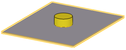
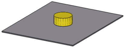
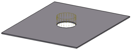
Cut objects with a part
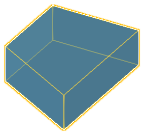
You can cut a part, or a rebar set, using another part. Note that you can cut parts that already have cuts. That can be useful, for example, when you want to create more sophisticated cut shapes. Tekla Structures displays the cut using dash-and-dot lines.
-
Select the object that you want to cut.
-
Select the cutting part.
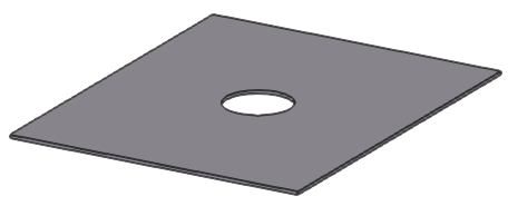
Using the cutting part, Tekla Structures creates the cut to the selected object. The part cut does not affect other objects.
-
Delete the cutting part.
-
Ensure that the
 Select cuts and added materials selection
switch is off.
Select cuts and added materials selection
switch is off.
- Select the cutting part and press Delete.
-
Ensure that the
Tips on how to cut efficiently
-
Avoid part faces
Avoid placing cut edges, cut vertices, or other cuts cutting the same part exactly at the same location as the edges or vertices of the part to be cut. Extend the cut outside of the part or other cut at least 0.3 mm. This practice helps you to avoid solid errors.
-
Use polygon cuts
Whenever possible, use polygon cuts. The Polygon cut command automatically extends the cut slightly outside of the part face in depth direction.
- Use edge chamfers
Whenever possible, use edge chamfers instead of small cuts, especially in components.
-
Tips for flange cuts of steel profiles
When cutting a flange, if the cutting part cuts very slightly the web as well (at least 0.3 mm), the cut is more likely to succeed. For example, if you are cutting a beam that has roundings, it may be useful to cut even further onto the web in depth direction than just the flange thickness.
-
Tips for round tube cuts
Use the Round tube (23) component for round tube cuts. The component automatically rotates the cutting part until a successful cut position is found. If the component fails, rotate the cutting part slightly until you find a successful cut position.
-
If a cut causes a solid error
If a cut causes a solid error, Tekla Structures is unable to render part faces and the part becomes transparent, only some edge lines being visible.
An error notification is printed in the session history log stating which part and which cut caused the failure.
To locate the failure in the model, click a row that contains a GUID identifier in the session history log. Tekla Structures selects the corresponding part and cut in the model.
To fix the error, move the problematic cut slightly (0.3 mm) to a different direction. If the cut is intersecting with other cuts, you can try to move also the other cuts.
Hide cuts in a model view
-
If you want to temporarily
display the hidden cuts in a model view:
- Select the part.
-
Click
 Display detailing on the contextual toolbar.
All the cuts of the selected part are displayed. To hide them again, redraw the view.
Polygon cut properties
Use the Polygon cut properties in the property pane to view and modify the properties of a polygon cut.
Note that the polygon cut properties are available in the property pane only after a polygon cut has been created and selected. You cannot access or modify the cut properties before the cut is created.
If you have customized the property pane layout, the list of properties may be different.
|
Setting |
Description |
|---|---|
|
General |
|
|
Name |
Name of the polygon cut. |
|
Profile |
Profile of the polygon cut, by default parametric profile BL. |
|
Material |
Material of the polygon cut, by default ANTIMATERIAL. The cut material cannot be changed. |
|
Class |
Use to group polygon cuts. |
|
Position |
|
|
At depth |
Position of the polygon cut in depth direction. |
|
More |
|
|
UDAs |
Click the User-defined attributes button to open the user-defined attributes (UDAs) of the cut. UDAs can be used to store more information for each cut, for example, to control the dimension creation in drawings. |
Part cut properties
Part cut uses the properties of the cutting part. For example, if the cutting part is a steel beam, part cut uses the Steel beam cut properties. The default part cut properties depend on the used cutting part.
If the cutting part is a hollow section, the cut is created with a similar, but non-hollow section, so that the inside of the cut is removed as well.
Note that the part cut properties are available in the property pane only after a part cut has been created and selected. You cannot access or modify the cut properties before the cut is created.