
Wall releases
You can apply releases to the top, bottom and edges of wall panels.
Wall top and bottom releases - overview
You can apply Minor Top and Minor Bottom releases to each panel of a meshed or midpier wall.
The top and bottom release options are:
-
Fixed
-
Pinned
-
Continuous (incoming members pinned) - note that this option is only available for meshed walls
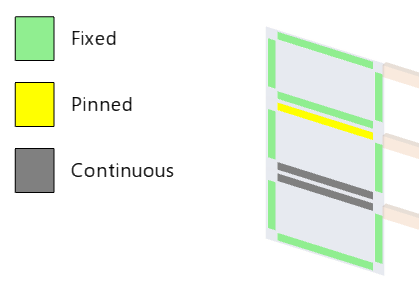
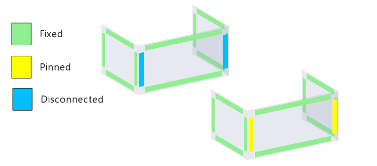
When wall releases are reviewed in a Review View colors are used to indicate the different edge conditions.
Tip:
To specify a pinned connection to a supported slab, use a meshed wall and select the Continuous (incoming members pinned) option.
This option is recommended because the Pinned option also releases the wall panel above from the wall panel below. This may result in a mechanism during the analysis.
Wall edge releases (meshed walls only) - overview
You can release each panel of a meshed wall at its edges, Edge 1 and Edge 2.
To identify the edges, select Walls > Direction in Scene Content.
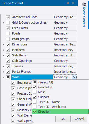
When you have selected Direction in Scene Content, an arrow displays on each wall starting at Edge 1 pointing towards Edge 2

The wall edge release options are:
| Edge 1, Edge 2 | Fixed degrees of freedom |
|---|---|
| Fixed (Default) | 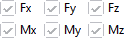 |
Pinned (released in My only)
|
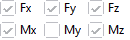 |
| Disconnected | 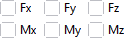 |
-
Fx – shear in plane of the wall perpendicular to the edge - could be an expansion joint
-
Fy – shear in plane of the wall along the edge - could be a vertical movement joint of some sort or part of a free edge
-
Fz – shear out of plane – horizontal joint of some sort or part of a free edge
-
Mx – moment about x
-
My – moment about the edge (fixed, pinned, or partially fixed)
-
Mz – moment about z
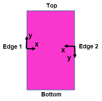
The sign convention for the degrees of freedom at the edges accords to the wall panel edge local coordinate system.
-
x is perpendicular to the edge in the plane of the wall panel (+ve towards the panel)
-
z is the wall panel normal
-
y is defined by right hand rule (along the edge)
When wall releases are reviewed in a Review View colors are used to indicate the different edge conditions.
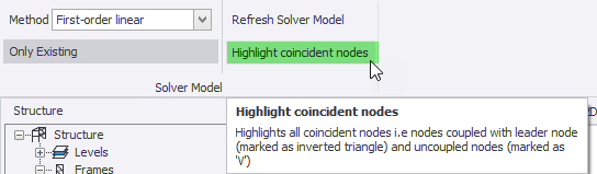
In the solver model, if a wall panel edge is Pinned or Disconnected and another wall panel or member connects to it, coincident solver nodes will be created. To help locate such nodes when in a Solver View, select Highlight coincident nodes on the Solver ribbon - this places arrows adjacent to the coincident nodes.
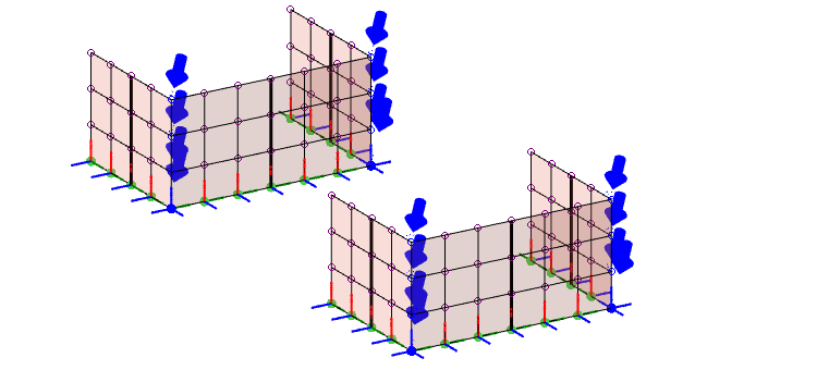
Where a pinned edge connects to a fixed edge, this is now modeled in Tekla Structural Designer using uncoupled coincident solver nodes connected by zero-length 1D solver elements. (In versions prior to Tekla Structural Designer 2026 coupled coincident solver nodes would have been used instead.)
You can see the impact of the release options that has been applied by opening a Results View and displaying 2D deflections.
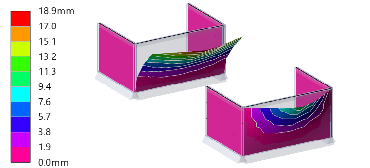
In the above example the wall with disconnected edges only deflects as it does because it has a free top edge.
As described in the following section, the presence of a rigid, or semi-rigid diaphragm, or a meshed slab will have a significant impact on how it deflects.
Disconnected walls attached to diaphragms or meshed slabs
If your model contains wall panels with disconnected edges, you should be aware of how they act when attached to diaphragms or meshed slabs.
Disconnected walls and diaphragms
-
Disconnected walls attached to the same diaphragm area (rigid or semi-rigid) will deflect by the same amount (or similar amount in the case of semi-rigid diaphragms) in the plane of the diaphragm
-
This will lead to sharing of load between disconnected walls
-
Lateral loads applied to a disconnected wall will not stay entirely within that wall if it is connected to other walls by diaphragms
-
This is no different to the case where real physical gaps exist between walls
-
-
The overall stiffness of the lateral load resisting system will however be reduced as expected when compared to walls that are not disconnected.
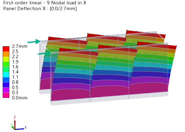
The above behaviour is illustrated by the following example in which a lateral load is applied to the first of three disconnected walls attached to a rigid diapragm.
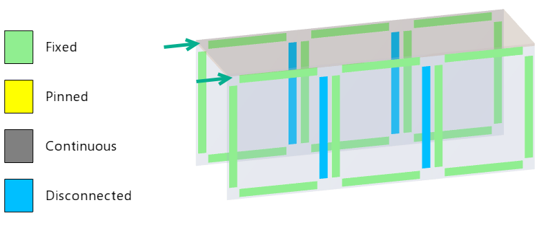
The load is shared between the walls and they all deflect by the same amount in the plane of the diaphragm.
Disconnected walls and meshed slabs
-
Where slabs are meshed in the 3D analysis they can always contribute to the lateral load resistance of the structure, they will create a frame system with columns and with walls. This applies equally when the walls have disconnected edges.
-
In general this is unlikely to be desirable and can be avoided by not setting the slabs to be meshed in 3D
-
In the case where it is for some reason considered desirable the results may show some FE mesh sensitivity.
Apply wall top and bottom releases
The recommended way to set wall releases is to apply them graphically from a Review View using the Show/Alter State Releases attribute.
If you don't want to use the graphical approach, you can also apply wall top and bottom releases using the Properties window or Properties dialog.
When using the Properties window the steps are as follows:
- Select the wall to be released.
- In the Properties window, go to Releases.
-
In the Minor Top or Minor Bottom list, select the desired release:
-
Fixed
-
Pinned
-
Continuous (incoming members pinned): only available for FE meshed walls
Tip:To specify a pinned connection to a supported slab, use an FE meshed wall and select the Continuous (incoming members pinned) option.
This option is recommended because the Pinned option also releases the wall panel above from the wall panel below. This may result in a mechanism during the analysis.
-
Apply wall edge releases
The recommended way to set wall releases is to apply them graphically from a Review View using the Show/Alter State Releases attribute.
If you don't want to use the graphical approach, you can also apply wall top and bottom releases using the Properties window or Properties dialog.
When using the Properties window the steps are as follows:
- Select the wall to be released.
- In the Properties window, go to Releases.
-
In the Edge
1 or Edge 2 list, select the desired
release:
-
Fixed
-
Pinned
-
Discontinuous
-