Footfall analysis basic workflow - SCI P354
The guidance in SCI P354 (Ref. 1) is almost entirely based on steel buildings with composite or precast floors. However, the footfall assessment process in Tekla Structural Designer can be performed on models of any material with floors of any construction type. Where the structure is not predominantly a steel building with composite or precast floors, it is the engineer’s responsibility to determine the applicability of the SCI P354 guide method, and thus the footfall assessment in Tekla Structural Designer which follows this, to their structure.
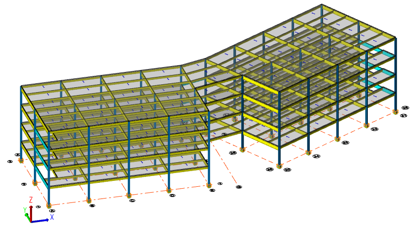
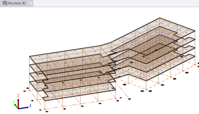
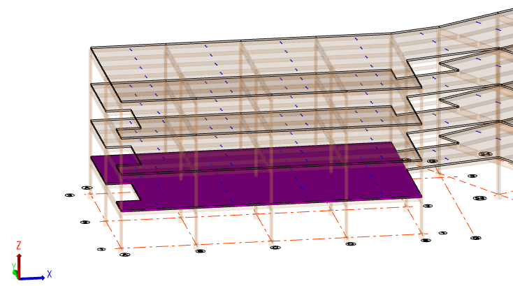
To illustrate the basic workflow when working to the SCI P354 design guide, the steel structure with composite floors shown below will be used.
Download and open the tutorial model
Open an appropriate view
- Open a Structure 3D Scene view.
-
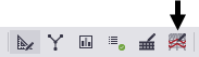
In the Status bar at the bottom of the main window, click the Footfall Analysis View regime button.
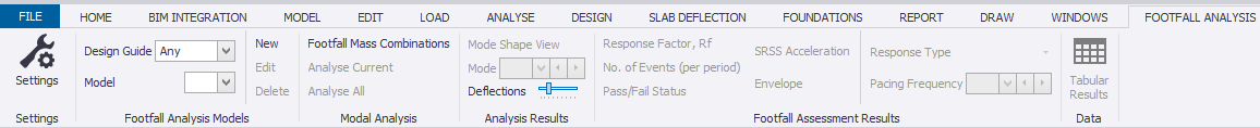
The Footfall Analysis ribbon becomes available, and the active view switches to a Footfall analysis view.
Tip:
Provided you have slab items displayed in an active Structural view, simply right-click a slab item and select Create Floor Analysis Model from the context menu - the Footfall analysis view is opened automatically with the selected slab highlighted and the rest of the floor ghosted.
Confirm the floor analysis model settings
-
On the Footfall Analysis ribbon, select Settings
The default settings are displayed. These are used to control the footfall analysis settings, analysis model settings, and modification factors for each available design guide. For more information, see: Footfall assessment settings
Initially there is a single settings set for the SCI P354 design guide, but you can add further sets to allow you to rapidly investigate different setting configurations.
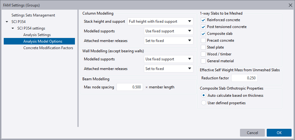
It is anticipated that most users will not need to adjust these settings from the default set up.
-
Click Cancel to exit.
Create a floor analysis model
-
On the Footfall Analysis ribbon, select New
-
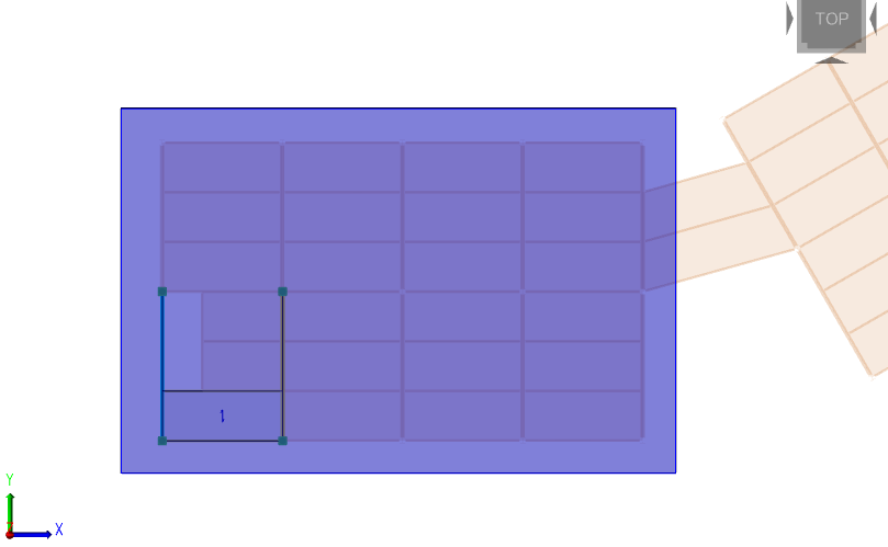
Select the slab item shown below as the first slab to include.
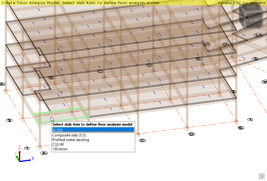
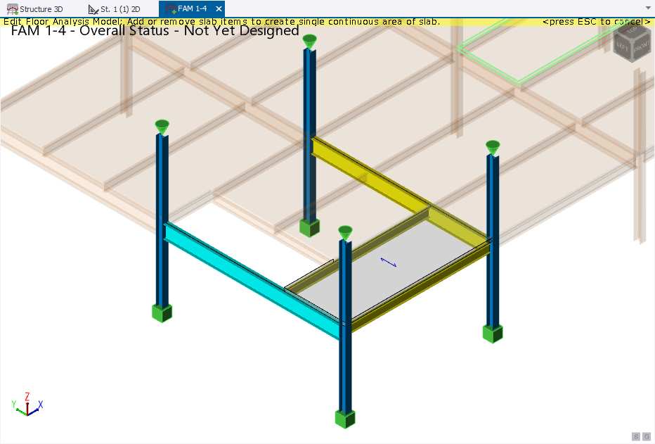
Once the first slab item has been selected a new Floor Analysis Model (FAM) view opens and the Floor Analysis Model (FAM) properties are displayed in the Properties window.
In this view further slab items can then be added to the model, either by clicking them individually, or by box selecting. Note that the Selection Mode in the Properties window, which defaults to ‘Add or Remove’ can also be set to ‘Add Only’ or ‘Remove Only’ to assist this process.
For this example we want the analysis model to comprise the entire left hand wing of the floor. The quickest way to achieve this is as follows:
-
In the Properties window, set the Selection Mode to ‘Add Only’
-
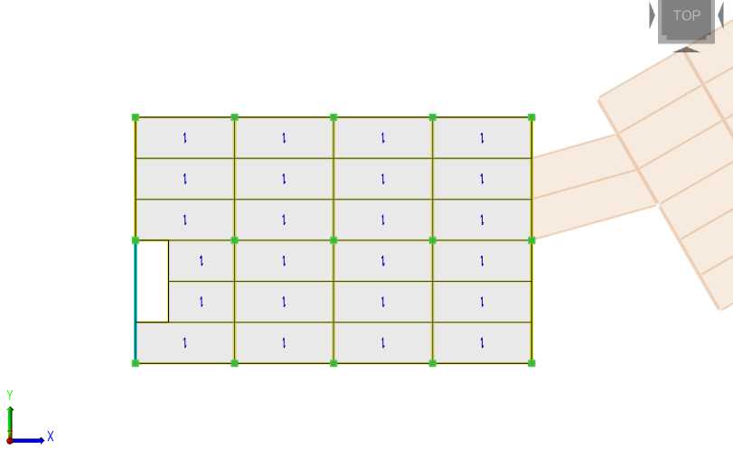
Change to a Top view and then drag a box around the slabs.
The slab items that comprise the analysis model should now be displayed as shown below:
Add and edit facade restraints
If required, facade restraints can be added very easily.
-
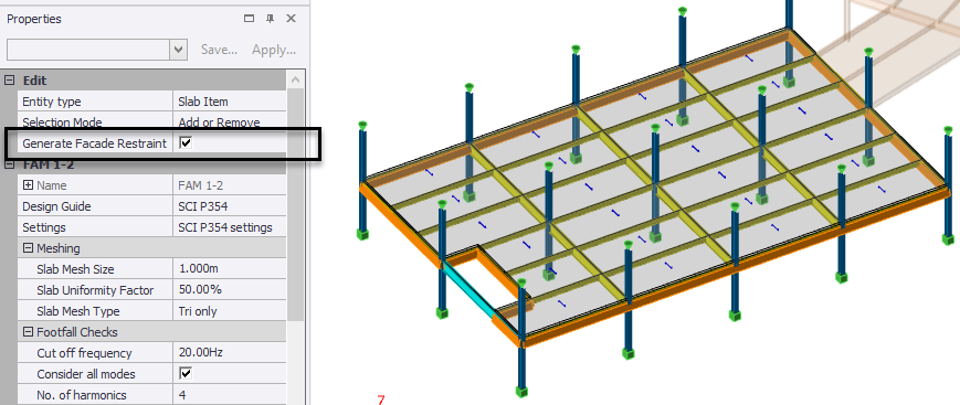
Select Generate Facade Restraint in the Properties window
Facade restraints are added around the entire perimeter of the selected slabs.
 Note:By changing the Entity type in the Properties window to Facade Restraint, you can then edit the restraints as required - simply clicking on a slab edge will add or remove its facade restraint.
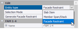
-
Press ESC on the keyboard to exit Edit mode.
Confirm the design guide, settings and meshing
Review the following properties located at the top of the Properties window.
- Ensure the Design Guide 'SCI P354' is selected.
- Ensure the Settings set 'SCI P354 settings' is selected.
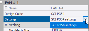
In a real model you could have created multiple FAM Settings sets, in which case you could then choose which set to apply.
- Review the meshing properties.
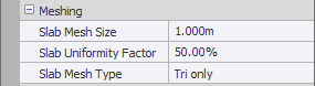
The mesh defaults are reasonable and will be left unchanged.
Create a Footfall mass combination
-
On the Footfall Analysis ribbon, select Footfall Mass Combinations.
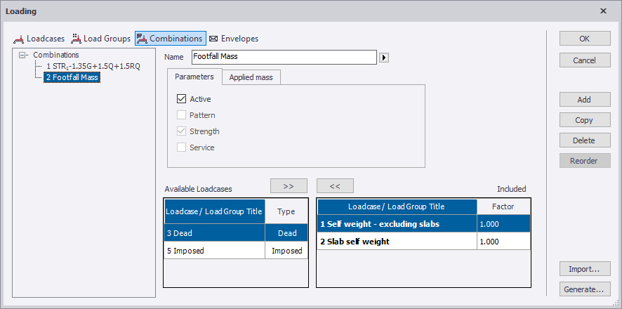
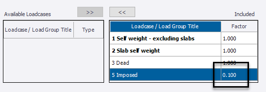
Any existing combinations for static design will be listed in this dialog followed by a Footfall Mass combination which is selected as shown above. Two loadcases have automatically been included in this combination.
At this point you complete the Footfall Mass combination by making appropriate selections from the list of available loadcases.
-
Include the Dead and the Imposed loadcases in the Footfall Mass combination.
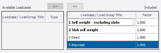
In real models engineering judgment will be required as the list of available loadcases can potentially be very long.
-
Set the Imposed loadcase factor to 0.100. (SCI P354 suggests 10% for imposed.)
- Click the Applied mass tab in the dialog.
No changes are required here, but note that for Footfall mass combinations, the applied mass defaults to being applied in the Z direction only.
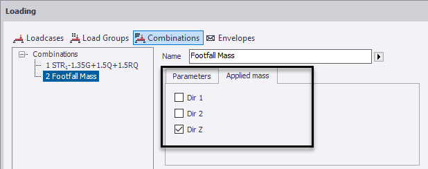
- Click OK to save the footfall mass combination.
Analyse the model and view the mode shapes
On the Footfall Analysis ribbon, there are two analysis choices:
-
Analyse Current - this runs a first-order modal analysis of the currently selected FAM for all active footfall mass combinations.
-
Analyse All - this runs a first-order modal analysis of all FAMs for all active footfall mass combinations.
As only one FAM has been created at this stage, it doesn’t actually matter which of the above two options is selected.
-
Click Analyse Current
Note:
The FE results you see may vary slightly depending on your installed service pack and may not exactly match the documentation.
View the mode shapes
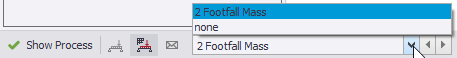
To view mode shapes graphically for the Footfall mass combination:
- Select the Footfall Mass combination in the Loading list.
-
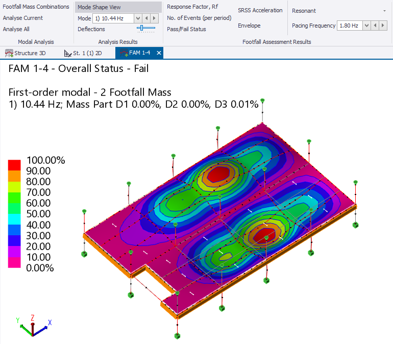
On the Footfall Analysis ribbon, select Mode Shape View.
-
To examine subsequent modes, select the required mode from the Mode list.
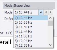
- To adjust the amplitude of the mode shape, drag the Deflections slider in the ribbon as required.
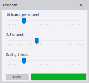
- To animate the mode shape, right-click in the view, and select Animate from the
context menu.
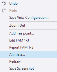
- To end the animation, close the Animation dialog.
Configure the footfall checks
Default SCI P354 footfall check
parameters for all models (predefined on the Footfall Assessment
> SCI P354 > Footfall Checks page in global settings) are automatically
copied into the Footfall Checks section of the Properties window for each FAM that is created.
The copied values can then be adjusted as required to suit the individual FAM.
For a detailed explanation of the above parameters, refer the SCI P354 Design Guide.(Ref. 1)
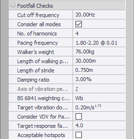
- Take a moment to review the footfall check values in the Properties window.
In this example we shall adjust the Length of walking path as the initial default (30m) is too conservative.
-
Set the Length of walking path to 7.5m.
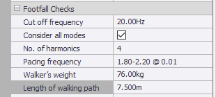
We shall accept all the other default values. Note that the default Target response factor is 4.0 so any nodes in the FAM with a greater response will be deemed to have failed.
If you were to change any of the above values, the Footfall Assessment results would update automatically - there is no need to re-perform the analysis.
View the footfall check results
Overall status
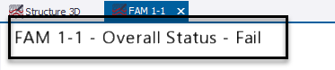
The overall status is
displayed in the top left corner of the FAM view.
Note that the status takes
into account any Mass Combination or Response Type filters
applied in the Overall Status & Envelopes section of the Properties window.
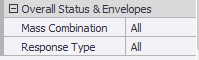
By default, all active footfall combinations are considered, and all (i.e. both resonant and transient) responses are considered.
As the overall status is 'Fail', this indicates that the target response factor has been exceeded for the resonant or the transient response at one or more pacing frequency.
View resonant and transient response factors at specific pacing frequencies
-
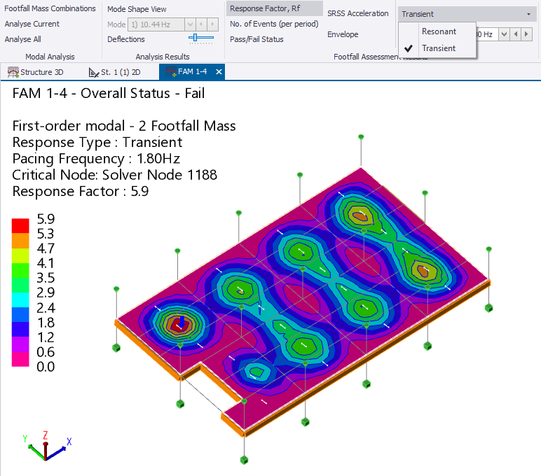
On the Footfall Analysis ribbon, select Response Factor, Rf
 Initially the Resonant response is displayed for the pacing frequency shown on the ribbon. You can select a different pacing frequency using the drop down option as shown below.
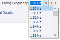
-
To examine the transient response for the selected pacing frequency, select Transient on the ribbon.
View response factor envelope
Note that envelopes take into
account any Mass Combination or Response Type filters applied
in the Overall Status & Envelopes section of the Properties window.
So by accepting the default filters as shown above, the response factor envelope allows us to locate the most critical response factor of either type (resonant or transient), for all pacing frequencies and all mass combinations (if more than one has been defined).
-
Select Envelope on the ribbon.
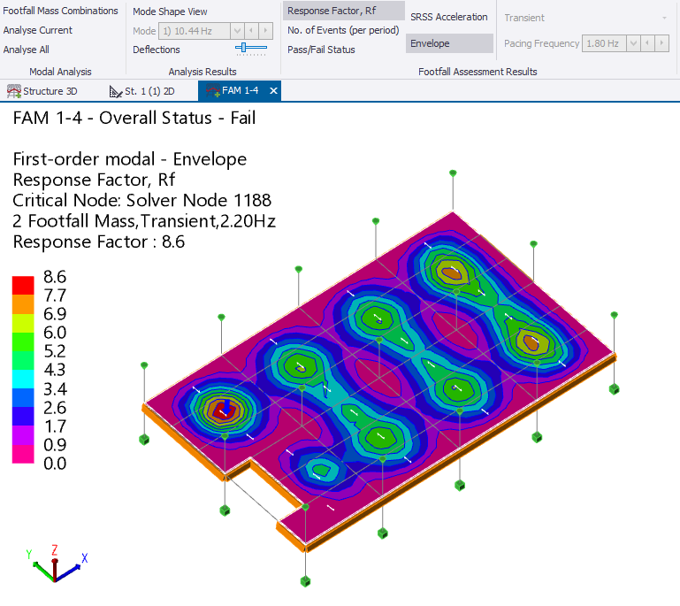
The above envelope reveals that the transient response is critical at a pacing frequency of 2.20Hz with a response factor of 8.6
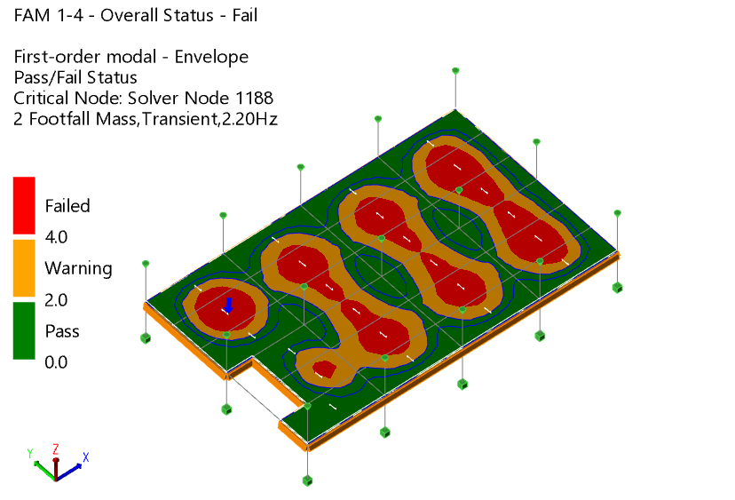
View Pass/Fail Status
To gain a better understanding of how wide an area is failing, the Pass/Fail status can be examined for the enveloped results.
On the ribbon:
- Ensure Envelope is still selected.
-
Select Pass/Fail Status
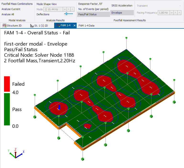
Every node has to be less than the Target response factor, Rf to achieve a pass status. Areas where nodal values are greater than the target are shown as failed.
View acceptable hotspots
Acceptable hotspots can be used to investigate
areas that fall between a general limit and the Target response factor.
-
In the Properties window, select Acceptable hotspots.
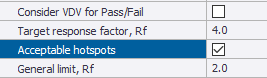
When acceptable hotspots are activated a General limit, Rf setting is added to the properties.
- Leave the General limit as 2.0
Regions with Rf values between the General limit and the Target response factor are then given a warning status.
Perform a VDV assessment
If the response factor fails you may be able to make a variable dose value (VDV) assessment instead. VDVs are always calculated, but by default they are not considered when determining the overall status.
For ease of use the VDV calculation procedure is ‘inverted’ so that the number of events (per period) equates to the number of times the walking path would need to be executed in order to generate an adverse response.
View the number of events at each node
To examine the number of events at the critical node:
-
On the Footfall Analysis ribbon, select No. of Events (per period).
Ensure Envelope is selected on the ribbon
The number of events at each node is displayed on a logarithmic scale. An arrow is used to identify where the critical node occurs.
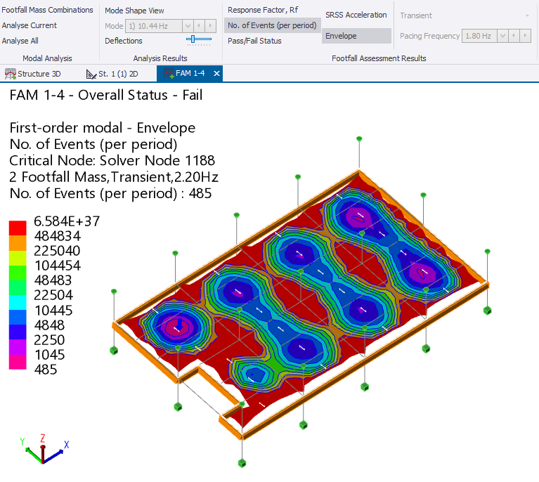
In the above display it can be seen that the critical number of events is 485. The arrow identifies the critical node where this occurs.
Activate the VDV assessment
When VDV is considered, the target number of events in a period that the client will accept has to be less than the Number of Events (per period) reported at the critical node.
-
In the Properties window, select Consider VDV for Pass/Fail.
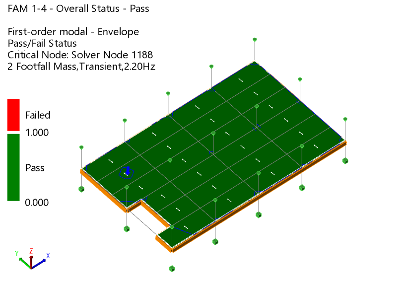
- Reduce the target number of events to 400.
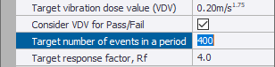
With these settings an overall pass status has been achieved.
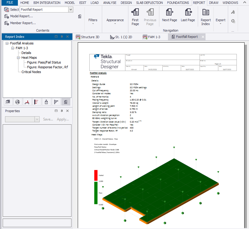
Output the calculations
A
Footfall Analysis report can be created as follows:
- On the ribbon, go to the Report tab.
- Click Model Report.
- In the Report Contents dialog, click Add and then under Active Style, enter a Name for the report
- In the list of chapters and options, select Footfall Analysis and drag it across to the Report Structure area.
- Click OK
- On the ribbon, in the list on the left side, select the report name you just created.
- Click Show Report.
Additional display and review options
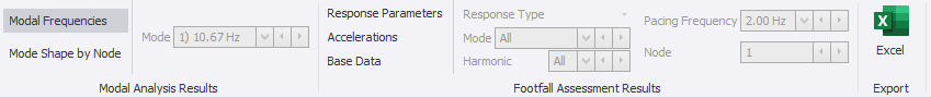
Several tabular data views are available, each of which can be exported to Excel.
To display the Floor Analysis Model Data ribbon from where the tabular data views can be accessed:
-
Make the Floor Analysis Model (FAM) view active once more.
-
On the Footfall Analysis ribbon, select Tabular Results

The Floor Analysis Model Data ribbon is displayed and an FAM tabular data view opens.
Modal Frequencies
To view modal frequencies, on the Floor Analysis Model Data select Modal Frequencies
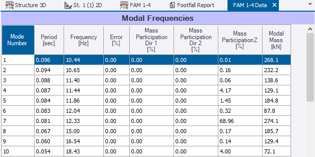
This table lists the period, frequency, mass participation, and modal mass for each mode.
Mode Shape by Node
To view mode shapes by
node:
- On the Floor Analysis Model Data ribbon, select Mode Shape by Node
- Select the required Mode from the list.
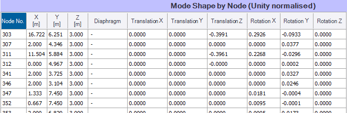
The mode shapes are listed for the selected mode.
Response Parameters
To view response
parameters:
- On the Floor Analysis Model Data ribbon, select Response Parameters
- Select the Resonant or Transient response type
- Select the Pacing Frequency from the list
-
In the Properties window, ensure the Footfall Checks parameters are specified as required.
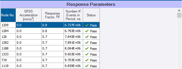
Note in particular:
- If Consider VDV for Pass/Fail is unchecked in the Properties window, the response factor is compared to the target response factor to determine the status.
- If Consider VDV for Pass/Fail is checked, the number of events are compared to the target number of events to determine the status.
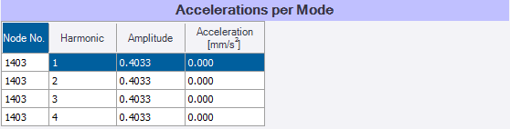
Accelerations
To view accelerations:
- On the Floor Analysis Model Data ribbon, select Accelerations
- Select the Resonant response type
- Select the required Mode from the list
- Select the required Pacing Frequency from the list
- Select the required Harmonic from the list
-
Select the required Node from the list
Base Data
To view base data:
-
On the Floor Analysis Model Data ribbon, select Base Data
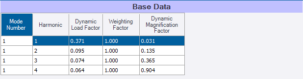
The choice of Resonant, or Transient, plus the Mode, Harmonic and Pacing Frequency to be displayed can be selected from the ribbon.
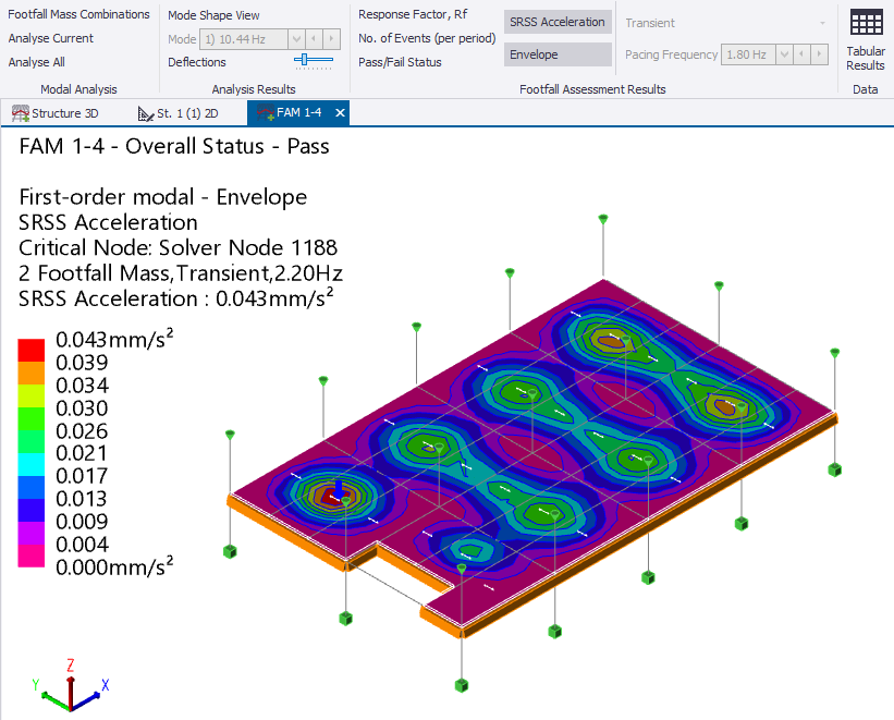
SRSS Acceleration
To graphically display SRSS Accelerations, return to the Floor Analysis Model (FAM) view and:
- On the Footfall Analysis ribbon, select SRSS Acceleration.
- Unselect Envelope and select Transient
The transient acceleration is shown and the critical node identified for the Footfall Mass combination selected in the Loading list.
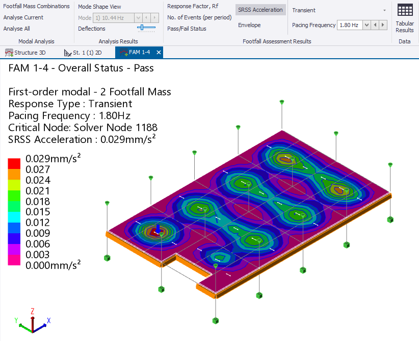
-
To consider all response types (resonant and transient), as well as all pacing frequencies and mass combinations (if more than one is defined), select Envelope.
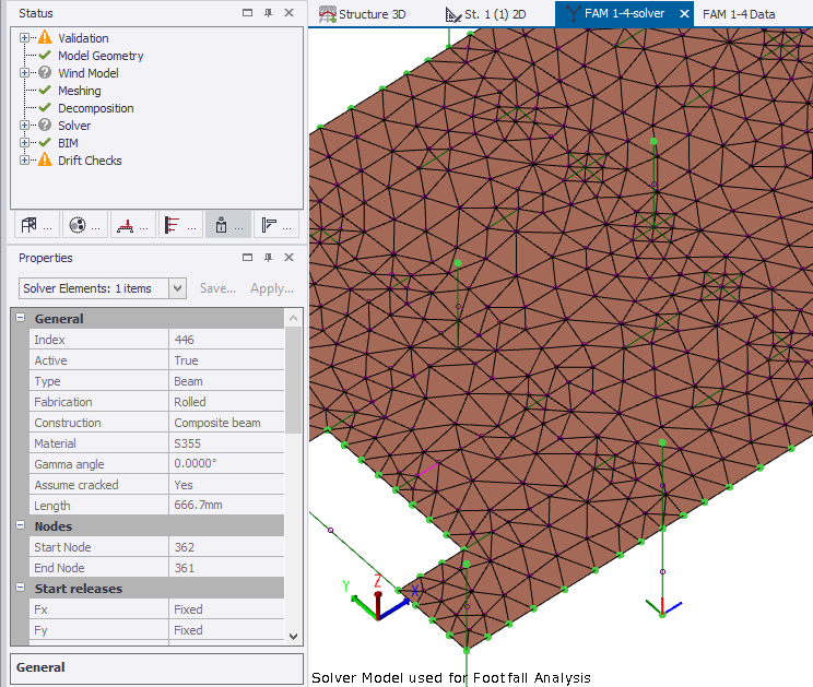
FAM solver model
After the analysis has been
performed, if you require you can examine the solver model used for the Footfall
Analysis model as follows:
- Ensure that the required Floor Analysis Model (FAM) view is active.
- To change the view type of the FAM view, do one of the following:
- Right-click the FAM view tab and in the context menu, select Solver view
- Or, in the Status bar at the bottom of the window, click Solver View.
- Right-click anywhere in the solver view.
- In the context menu, select Solver models.
- In
the submenu, select Solver Model used for Footfall Analysis.
Tekla Structural Designer opens the selected solver model. You can then select individual elements in the solver model to display their section and material properties in the Properties window.
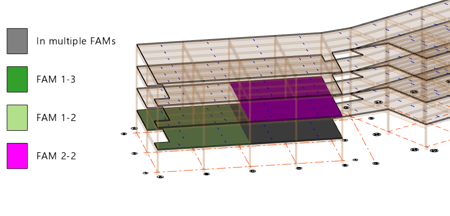
Create additional floor analysis models, edit or delete models
When the Structure 3D view is active and set to the Footfall Analysis View regime it will display all the floor analysis models that have been created so far.
You can continue to define as many FAM’s as you wish in a similar manner, on the same or other levels. Slab items can be in more than one FAM. For example you might create a single FAM for a very large floor area which will expose areas of interest which might then be investigated with other more localized FAMs.
The following options are available:
-
Click on an existing model in order to edit it in a FAM view.
-
Select New in the ribbon to start a new model
-
Select Delete in the ribbon, then click on an existing model in order to delete it.