SidePlate connections theory
2020
Tekla Structural Designer
SidePlate connections theory
Overview of SidePlate connections
SidePlate® is a type of moment connection for connecting I or HSS section beams to I, HSS, built up box or built up WF (cruciform) section columns.
SidePlates are welded to the column section in the fabrication shop. Plates or angles are similarly welded to beam ends.
The column and beam units are transferred to site where the columns are erected and the beams are lifted into place and either bolted or welded to the columns. SidePlate connections are used on buildings of 1 to 30 stories tall.
Within the structure, the beam end is held in position by SidePlates. The net result is moment connection with a very stiff section of column and a stiffened beam end.
SidePlate connection types can be:
-
Non-Seismic moment connections
-
A beam/column moment connection anywhere in the structure
-
-
Seismic moment connections
-
A seismic beam/column moment connection within any of the following seismic force resisting systems Ordinary Moment Frame (OMF), Intermediate Moment Frame (IMF) or Special Moment Frame (SMF).
-
SidePlate connections work for all WF and HSS sections in the AISC steel book, and for all UB and UKB sections. However it is worth noting the SidePlate datafile may NOT have a full set of values for all 'clear spans' or all %Mps for all these sections; if this is the case then no SidePlate connection can be applied at the joint.
Tekla Structural Designer can perform an initial sizing for the SidePlate connection, but the final detailed design of the SidePlate connection has to be undertaken in SidePlate® software.
Permitted SidePlate connections in Tekla Structural Designer
Restriction: In Tekla Structural Designer, sideplate connections are currently only permitted for US Customary sections and not for metric sections.
| Column | Side Plate Permitted Connections | Tekla Structural Designer Status | |||||
|---|---|---|---|---|---|---|---|
| Non-Seismic Moment Connections | Seismic Moment Connections | ||||||
| Beam | Beam | ||||||
| I | HSS | I | HSS | ||||
| WF | Flange | yes | yes | yes | yes |  |
Modeled Analyzed Designed |
| Web | yes | yes | Warning | Warning | |||
| HSS | Flange | yes | yes | yes | yes |  |
Modeled Analyzed Designed |
| Web | yes | yes | yes | yes | |||
| Plated box | Flange | yes | yes | yes | yes |  |
Modeled Analyzed Not Designed |
| Web | yes | yes | yes | yes | |||
| WF + 2xWT | Flange | yes | yes | yes | yes |  |
Not Modeled Not Analyzed Not Designed |
| Web | yes | yes | yes | yes | |||
| WF + 1xWT | Flange | yes | yes | yes | yes |  |
Not Modeled Not Analyzed Not Designed |
| Web | yes | yes | Warning | Warning | |||
SidePlate workflow in Tekla Structural Designer
A brief description of the SidePlate workflow in Tekla Structural Designer is given here with more detail available in the subsequent topics.
- Modeling: You define SidePlate connections by changing properties of the relevant beam or beams.Note: The Update Connections process used for defining other connection types is not applicable for SidePlate.
Connection objects are not created for any point on a steel column where any of the beams attached at that point have a SidePlate connection.
-
Visualisation: Each connection is initially shown in the graphics as a simple box. After sizing has been performed it is shown as a pair of plates.
-
Validation: Some preliminary checks are carried out in Model validation, (additional checks are done subsequently in Initial sizing and Analysis model adjustment). Any problems do not stop the analysis and design process but mean the relevant beam and or column will not benefit from the enhanced properties.
- Initial sizing: The initial SidePlate dimensions are determined during the Design Steel (Static & RSA) and Design All (Static & RSA) processes, using data provided by SidePlate and incorporated into Tekla Structural Designer.Note: After the initial sizing process, any changes to loading, (individual loads, load cases and combinations), will not trigger change control for the SidePlates, i.e. they will keep those initial sizes. You can reset the status using Review mode if you decide that the sizing process needs to be run again.
-
Analysis model adjustment: Where valid SidePlate dimensions exist, the analysis model passed to the solver is adjusted to reflect the increased stiffness of the SidePlate connections. This is done during stand-alone analysis as well as Design.
-
Steel member design: If SidePlate connections exist, they are taken into account in the member design for steel beams and columns. The changes affect both static and seismic design.
-
Review: The SidePlate connection status can be seen easily in a Review view, and tooltips give more information.
-
Reports: A “SidePlate Connection Report” can be generated.
- Final design: SidePlate developers can use the Tekla Structural Designer API in order to fully design a SidePlate connection defined and initially sized in Tekla Structural DesignerNote: Design of SidePlate connections is beyond scope for both Tekla Connection Designer and export to the IDEA StatiCa Connection Design program.
SidePlate 'joint' and 'connection' terminology
Note:
- A SidePlate joint exists at a column node and consists of 1 to 4 valid connections.
- Every suitable beam framing into the column node can create a SidePlate connection.
A SidePlate connection exists at End 1 and / or End 2 of a steel beam where Apply SidePlate Connection is true. It will still exist even if other data makes it invalid. The connection position is the reference point at the relevant end of the beam.
All connections sharing the same position on a column are considered as a single SidePlate Joint. No attempt is made to merge separate SidePlate joints even where the relevant levels are close.
Various checks are performed on each connection and each joint, and the analysis model is only be adjusted if they all pass. In particular, if the depths of two SidePlate joints overlap then a warning is generated and the analysis model is not be adjusted.
SidePlate validation
SidePlate validation is performed during model validation.
If warnings are issued, this will typically result in the Connection Status being set to "Not Applied" in the Properties window.
Note: Until the “Not Applied” Connection Status is resolved, the connection will not be considered for the initial sizing process.
Initial sizing of the SidePlates
The initial SidePlate dimensions are determined during the Design Steel (Static & RSA) and Design All (Static & RSA) processes.
The initial sizing process is only performed where the Sizing Status is “Not Performed” and the Connection Status is not “Not Applied”.
For each connection that is considered, a number of checks are performed in order to verify that SidePlate can be applied. If any of the checks fail, the Connection Status is set to "Not Applied".
Note: After the initial sizing process, any changes to loading, (individual loads, load cases and combinations), will not trigger change control for the SidePlates, i.e. they will keep those initial sizes. You can reset the status using Review mode if you decide that the sizing process needs to be run again.
Analysis model adjustment
Analysis model adjustment is only performed for valid SidePlate connections that have successfully completed the initial sizing process, i.e. where the Sizing Status is not “Not Performed”.
Both the geometry and the properties of the Solver model are dependent upon the size of the SidePlate connection.
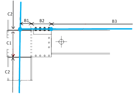
For the beam
- B2 – a new 1d element on the beam, with stiffened beam properties.
- B1 – a rigid offset on the end of B2
- B3 – normal bare beam properties
For the Column
- C1 – a rigid offset at the top of the column 1d element
- C2 – normal column properties
Design/Analysis processes and recommended workflows
Tekla Structural Designer can automatically size members throughout a structure – we call this Autodesign. The process is complex and involves sophisticated initial sizing, multiple analysis runs with repeated design cycles. The interweaving of initial sizing for SidePlate connections into the Autodesign routines is a highly complex process and for the first implementation remains beyond scope. Instead you have to manually reduce section sizes to take advantage of the SidePlate advantages.
Any beams and columns not affected by SidePlate connections can be AutoDesigned as normal during this process.
The following examples show the results for 2 different workflows where each step is carried out in the exact order specified and assuming that there are no model issues.
Recommended Workflow
-
Full model created including loadcases and combinations - AutoDesign left checked for all columns, beams etc.
-
Check “Apply SidePlate Connection” for selected beams - also set Utilization Ratio to 1.25 for those beams.
-
Set Utilization Ratio to 1.1 for selected columns
-
Run 1st order linear analysis
-
Validation will generate SidePlate AutoDesign warnings where relevant
-
SidePlate Initial Sizing will not be performed because not Static Design
-
Adjust Solver Model will not be performed because no Connections will have Sizing Status not “Not Performed”.
-
-
Run Gravity Design Steel
-
Validation will generate SidePlate AutoDesign warnings where relevant
-
SidePlate Initial Sizing will not be performed because not Static Design
-
Adjust Solver Model will not be performed because no connections will have Sizing Status not “Not Performed”.
-
-
Reset Utilization Ratio to 1.0 for relevant beams and columns
-
Run Static Design Steel
-
No SidePlate related validation warnings
-
SidePlate Initial Sizing is performed for all connections
-
Adjust Solver Model will be performed for subsequent analysis
-
-
Manually adjust section sizes to achieve further size savings with SidePlate connections
-
SidePlate Connection Status will be reset where necessary
-
-
Run Static Design Steel
-
No SidePlate related validation warnings
-
SidePlate Initial Sizing is performed only where section sizes have been changed
-
Adjust Solver Model will be performed
-
At the end of this workflow, any subsequent stand-alone analysis will also use the adjusted solver model.
Other Workflow
-
Full model created including loadcases and combinations - AutoDesign left checked for all columns, beams etc.
-
Check “Apply SidePlate Connection” for selected beams.
-
Run Static Design Steel
-
Validation will generate SidePlate AutoDesign warnings where relevant
-
SidePlate Initial Sizing will not be performed because Connection Status will be set to Warning
-
Adjust Solver Model will not be performed because no Connections will have Sizing Status not “Not Performed”.
-
-
Run Static Design Steel
-
No SidePlate related validation warnings
-
SidePlate Initial Sizing is performed for all Connections
-
Adjust Solver Model will be performed for subsequent analysis
-
Effects of SidePlate on steel member design
Any beams and columns not affected by SidePlate connections can be AutoDesigned as normal.
Beams and columns affected by SidePlate connections cannot be AutoDesigned.
Where SidePlate connections exist, changes are required for both static and seismic member design.
For static design
- Beam and column buckling lengths are affected.
- Beam and column design checks are adjusted so that they are applied outside the physical length of any SidePlate connection
For seismic design
- OMF frames - no change
- IMF frames – various changes
- SMF frames – various changes